
HP XC System Software Hardware Preparation Guide Version 4.0
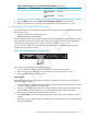

2. Turn on power to the node. Watch the screen carefully during the power-on, self-test, and
press the F10 key when prompted to access the BIOS Setup Utility. The Lights-Out 100i
(LO-100i) console management device is configured through the BIOS Setup Utility.
The BIOS Setup Utility displays the following information about the node:
BIOS ROM ID:
BIOS Version:
BIOS Build Date:
Record this information for future reference.
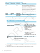
3. For each node, make the following BIOS settings from the Main window.
Table 4-3 lists the BIOS settings for HP ProLiant DL140 G3 nodes.
Table 4-3 BIOS Settings for HP ProLiant DL140 G3 Nodes
Set to This ValueOption NameSubmenu NameMenu Name
Disabled
NumlockBoot FeaturesMain
Disabled
8042 Emulation
Support
Advanced
BMC
Serial PortI/O Device
Configuration
Enabled
Console RedirectionConsole Redirection
Enabled
EMS Console
115.2K
Baud Rate
Enabled
Continue C.R. after
POST
DHCP
IP Address
Assignment
IPMI/LAN Settings
Enabled
BMC Telnet Service
Enabled
BMC Ping Response
Enabled
BMC HTTP Service
Enabled
BMC HTTPS Service
Set the following boot order on the head
node:
1. CD-ROM
2. Removable Devices
3. Hard Drive
4. Embedded NIC1
5. Embedded NIC2
Boot
Set the following boot order on all nodes
except the head node:
1. CD-ROM
2. Removable Devices
3. Embedded NIC1
4. Hard Drive
5. Embedded NIC2
Enabled
Embedded NIC1
PXE
Disabled
Embedded NIC2
PXE
64 Preparing Individual Nodes