
HP XC System Software Hardware Preparation Guide Version 4.0
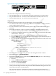
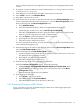
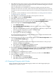
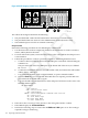

Figure 4-28 HP Integrity rx2660 Server Rear View
21 3
The callouts in the figure enumerate the following:
1. The LAN port labeled Gb 1 connects to the Administration Switch (branch or root).
2. The LAN port labeled Gb 2 is used for an external connection.
3. The port labeled MP LAN is the MP connection to the ProCurve Console Switch.
Setup Procedure
Perform the following procedure on each HP Integrity rx2660 server:
1. Use the instructions in the accompanying hardware documentation to connect a monitor,
mouse, and keyboard to the node.
2. For each node in the system, ensure that the power cord is connected but that the processor
is not turned on.
3. Follow this procedure to connect a personal computer to the Management Processor (MP):
a. Connect a cable to the console port (located to the left of the MP LAN port) on the back
of the HP Integrity rx2660 server.
b. Connect the CONSOLE connector to a null modem cable, and connect the null modem
cable to the PC COM1 port.
c. Use a terminal emulator, such as HyperTerminal, to open a terminal window.
d. Press the Enter key to access the MP. If the MP does not respond, press the MP reset
pin on the back of the MP and try again.
e. Log in to the MP using the default user name and password shown on the screen. The
MP Main Menu appears:
MP MAIN MENU:
CO: Console
VFP: Virtual Front Panel
CM: Command Menu
SMCLP: Server Management Command Line Protocol
CL: Console Log
SL: Show Event Logs
HE: Main Help Menu
X: Exit Connection
4. Enter SL to show event logs. Then, enter C to clear all log files and Y to confirm.
5. Enter CM to display the Command Menu.
6. Perform the following steps to ensure that the IPMI over LAN option is set. This setting is
required for Nagios monitoring.
a. Enter SA.
b. Verify the IPMI over LAN option is enabled.
c. Enable this option if it is disabled.
d. Return to the Command Menu.
128 Preparing Individual Nodes