
HP XC System Software Installation Guide Version 3.0
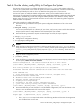
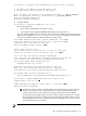
node: n16 location: Level 1 Switch 172.20.65.1, Port 42
CURRENT HEAD NODE
roles assigned: management_server management_hub external disk_io compute
External Ethernet Name: penguin.southpole.com, ipaddr: 192.0.2.0, netmask:
255.255.252.0, gateway: 192.0.2.51
node: n15 location: Level 1 Switch 172.20.65.1, Port 41
roles assigned: resource_management compute
The following nodes are configured with the common role "compute":
n[11-15]
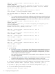
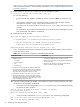
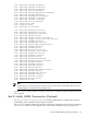
• [A]ll output looks similar to the following and displays specific information about the head node
and each client node. Be aware that output can be quite lengthy on a system with a large number
of nodes. For example, the output for a 500 node system with 495 compute-only nodes results in
approximately 1500 lines of output.
node: n16 location: Level 1 Switch 172.20.65.1, Port 22
CURRENT HEAD NODE
roles assigned: compute disk_io external management_hub management_server
resource_management
External Ethernet Name: penguin.southpole.com, ipaddr: 192.0.2.0,
netmask: 255.255.252.0, gateway: 192.0.2.51
node: n15 location: Level 1 Switch 172.20.65.1, Port 21
roles assigned: compute
node: n14 location: Level 1 Switch 172.20.65.1, Port 20
roles assigned: compute
node: n13 location: Level 1 Switch 172.20.65.1, Port 19
roles assigned: compute
node: n12 location: Level 1 Switch 172.20.65.1, Port 18
roles assigned: compute
node: n11 location: Level 1 Switch 172.20.65.1, Port 17
roles assigned: compute
Continue? [y/n] y
7. Do the following:
a. See Chapter 8 (page 91) for a description of the default role assignments based on system size.
Also, read about the special considerations regarding the default role assignments to determine
if they are suitable for your environment. If you do not modify the role assignments, your system
will be configured with the default assignments.
After reading this information, determine if you are satisfied with this configuration or if you want
to modify role assignments.
b. If necessary, refer to Appendix F (page 117), and use the Modify Nodes and Analyze options
to adjust the role assignments or create an external Ethernet connection on any node.
c. When you are satisfied with the role assignments and Ethernet connections, continue to step 8.
8. When you are satisfied with the current system configuration, enter the letter p to apply it to the system:
[L]ist Nodes, [M]odify Nodes, [A]nalyze, [H]elp, [P]roceed, [Q]uit: p
Do you want to apply your changes to the cluster configuration? [y/n] y
9. Do one of the following when this prompt is displayed:
[S]ervices Config, [P]roceed, [Q]uit:
52 Configuring and Imaging the System