
HP XC System Software Installation Guide Version 3.0
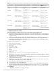
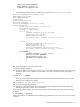
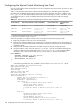

Table D-2 Quadrics Switch Controller Card Naming Conventions and IP Addresses For Full Bandwidth
Top-Level Switch IP
Address
Top-Level Switch NameNode-Level IP AddressNode-Level Switch NameNumber of Nodes
Not applicableNot applicable(P)
1
172.20.66.1
(S)
2
172.20.66.2
QR0N00
QR0N00_B
1 to 64
172.20.66.9 and
172.20.66.10
172.20.66.11 and
172.20.66.12
QR0T00 to QR0T01
QR0T00_B to QR0T01_B
(P) 172.20.66.1 to
172.20.66.4
(S) 172.20.66.5 to
172.20.66.8
QR0N00 to QR0N03
QR0N00_B to QR0N03_B
65 to 256
(P) 172.20.66.17 to
172.20.66.20
(S) 172.20.66.21 to
172.20.66.24
QR0T00 to QR0T03
QR0T00_B to QR0T03_B
(P) 172.20.66.1 to
172.20.66.8
(S) 172.20.66.9 to
172.20.66.16
QR0N00 to QR0N07
QR0N00_B to QR0N07_B
257 to 512
(P) 172.20.66.33 to
172.20.66.40
(S) 172.20.66.41 to
172.20.66.48
QR0T00 to QR0T07
QR0T00_B to QR0T07_B
(P) 172.20.66.1 to
172.20.66.16
(S) 172.20.66.17 to
172.20.66.32
QR0N00 to QR0N15
QR0N00_B to QR0N15_B
513 to 1024
172.20.66.65 to
172.20.66.127
Secondary not applicable
QR0T00 to QR0T63
Secondary not applicable
(P) 172.20.66.1 to
172.20.66.32
(S) 172.20.66.33 to
172.20.66.64
QR0N00 to QR0N31
QR0N00_B to QR0N31_B
1025 to 2048
1 (P) represents the primary switch controller.
2 (S) represents the secondary switch controller.
Follow this procedure to configure network access to the Quadrics switch controller card:
1. Ensure that an Ethernet cable from the monitoring line card's primary Ethernet port is connected to an
Ethernet port on the Root Administration Switch. This connection is described in the
HP XC Hardware
Preparation Guide
.
2. Connect to the switch controller using a VGA monitor and keyboard or a connection to the serial port
using a null modem cable and a terminal or terminal emulation program such as HyperTerminal.
Connecting to the switch controller displays the Quadrics Switch Control main menu, which
looks similar to the following:
Quadrics Switch Control -- (QR0N00)
1. Show network settings
2. Change network settings
3. Run jtest
4. Set module mode
5. Firmware upgrade
6. Quit
7. Reboot
8. Access Settings
9. Self Test
3. Select the Change network settings menu option and select BOOTP.
4. Select the Show network settings menu option to obtain the line card MAC address. Write down
this address for use later in this procedure.
5. Select the Access Settings menu option, and select the Password settings menu option to set
a login password for the switch.
6. Select the Access settings menu option again, and select the Access protocol settings
menu option to enable the telnet and ssh commands.
7. Reboot the switch controller from the Reboot menu option.
8. Log in as the root user on the head node.
9. Use the text editor of your choice to open the /etc/dhcpd.conf file, and add the following lines
anywhere inside the configuration block that begins with shared-network XC {. Enter the MAC
address obtained in step 4, and use the number zero (0), not the letter O, in the host name QR0N00:
host QR0N00 {
hardware ethernet your_MAC_address;
106 Configuring Interconnect Switch Monitoring Cards