
HP XC System Software Hardware Preparation Guide Version 3.2
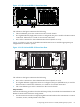
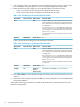
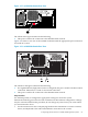
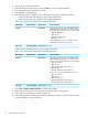
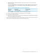
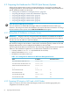

Figure 4-13 HP ProLiant DL585 G1 Server Rear View
!
1
2
133M H z
12345678
PCI -X
64-
B i t
100M
Hz
12
iL O
2
1
UID
The callouts in the figure enumerate the following:
1. The iLO Ethernet port is the connection to the Console Switch.
2. If a Gigabit Ethernet (GigE) interconnect is configured, this port is used for the interconnect
connection. Otherwise, it is used for an external connection.
3. NIC1 is the connection to the Administration Switch (branch or root).
Figure 4-14 shows a rear view of the HP ProLiant DL585 G2 server and the appropriate port
assignments for an HP XC system.
Figure 4-14 HP ProLiant DL585 G2 Server Rear View
UID
23 1
The callouts in the figure enumerate the following:
1. NIC1 is the connection to the Administration Switch (branch or root).
2. If a Gigabit Ethernet (GigE) interconnect is configured, this port (labeled NIC2) is used for
the interconnect connection. Otherwise, it is used for an external connection.
3. The iLO2 Ethernet port is the connection to the Console Switch.
Setup Procedure
Perform the following procedure from the iLO Setup Utility for each HP ProLiant DL585 G1 and
DL585 G2 node in the hardware configuration:
1. Use the instructions in the accompanying HP ProLiant hardware documentation to connect
a monitor, mouse, and keyboard to the node.
4.7 Preparing the Hardware for CP4000 (AMD Opteron) Systems 81