
HP XC System Software Hardware Preparation Guide Version 3.2


1. The iLO Ethernet is the port used as the connection to the Console Switch.
2. NIC1 is used for the connection to the Administration Switch (branch or root).
3. NIC2 is used for the external connection.
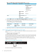
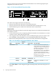
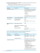
Figure 4-3 shows a rear view of the HP ProLiant DL360 G5 server and the appropriate port
assignments for an HP XC system.
Figure 4-3 HP ProLiant DL360 G5 Server Rear View
3
2
1
The callouts in the figure enumerate the following:
1. This port is used for the connection to the Console Switch.
2. This port, NIC1, is used for the connection to the Administration Switch (branch or root).
3. The second onboard NIC is used for the Gigabit Ethernet interconnect or for the connection
to the external network.
Setup Procedure
Perform the following procedure from the iLO Setup Utility for each HP ProLiant DL360 G4 and
G5 node in the HP XC system:
1. Use the instructions in the accompanying HP ProLiant hardware documentation to connect
a monitor, mouse, and keyboard to the node.
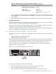
2. Turn on power to the node. Watch the screen carefully during the power-on self-test, and
press the F8 key when prompted to access the Integrated Lights Out Setup Utility.
3. For each node, make the iLO settings listed in Table 4-5.
Table 4-5 iLO Settings for HP ProLiant DL360 G4 and G5 Nodes
Set to This ValueOption NameSubmenu NameMenu Name
Create a common iLO user name and password for
every node in the hardware configuration. The
password must have a minimum of 8 characters by
default, but this value is configurable.
The user Administrator is predefined by default,
but you must create your own user name and
password. For security purposes, HP recommends
that you delete the Administrator user.
You must use this user name and password to
access the console port.
AddUser
On
DHCP EnableDNS/DHCPNetwork
115200 (Press the F10 key to save the setting.)Serial CLI Speed
(bits/seconds)
CLISettings
4. Select File→Exit to exit the Integrated Lights Out Setup Utility and resume the power-on
self-test.
5. Watch the screen carefully, and press the F9 key when prompted to access the ROM-Based
Setup Utility (RBSU).
Perform the following procedure from the RBSU for each node in the hardware configuration:
4.5 Preparing the Hardware for CP3000 (Intel Xeon with EM64T) Systems 55