
HP XC System Software Hardware Preparation Guide Version 3.2
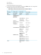
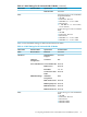
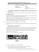
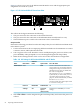
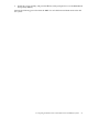
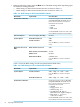

Table 4-4 BIOS Settings for HP ProLiant DL140 G3 Nodes (continued)
Set to This ValueOption NameSubmenu NameMenu Name
Set the following boot order on all nodes
except the head node:
1. CD-ROM
2. Removable Devices
3. Embedded NIC1
4. Hard Drive
5. Embedded NIC2
Enabled
Embedded NIC1
PXE
Disabled
Embedded NIC2
PXE
Off
Resume On Modem
Ring
Power
Disabled
Wake On LAN
4. From the Main window, select Exit→Save Changes and Exit to exit the utility.
5. If the DL140 G3 node uses SATA disks, you must disable the parallel ATA option; otherwise,
the disk might not be recognized and imaged.
Use the following menus to disable this option:
Set to This ValueOption NameSubmenu NameBIOS Menu Name
Disabled
Parallel ATAAdvanced Chipset
Control
Advanced
6. Repeat this procedure for each HP ProLiant DL140 G2 and G3 node in the HP XC system.
4.5.2 Preparing HP ProLiant DL360 G4 and G5 Nodes
Use the following tools to configure the appropriate settings for HP ProLiant DL360 G4 and G5
servers:
• Integrated Lights Out (iLO) Setup Utility
• ROM-Based Setup Utility (RBSU)
HP ProLiant DL360 G4 and G5 servers use the iLO utility; thus, they need certain settings that
you cannot make until the iLO has an IP address. The HP XC System Software Installation Guide
provides instructions for using a browser to connect to the iLO to enable telnet access.
Figure 4-2 shows a rear view of the HP ProLiant DL360 G4 server and the appropriate port
assignments for an HP XC system.
Figure 4-2 HP ProLiant DL360 G4 Server Rear View
11
The callouts in the figure enumerate the following:
54 Preparing Individual Nodes