
HP XC System Software Hardware Preparation Guide Version 3.0
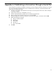

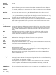


Figure 3-13 HP Integrity rx4640 Server Rear View
HPTC-0146
1 2 3
The callouts on Figure 3-13 enumerate the following:
1. The port labeled MP LAN is the MP connection to the ProCurve Console Switch.
2. The port labeled LAN Gb connects to the Administration Switch (branch or root).
3. This unlabeled port is used for an external connection.
Tasks
Perform the following hardware preparation tasks on each HP Integrity rx2620 and rx4640 server in your
HP XC system:
1. For each node in the HP XC system, ensure that the power cord is connected but that the CPU is not
turned on.
2. Follow this procedure to connect a personal computer (PC) to the Management Processor:
a. Connect a three-way DB9–25 cable to the MP DB-25 port on the back of the HP Integrity rx2600
server.
b. Connect the CONSOLE connector to a null modem cable, and connect the null modem cable to
the PC COM1 port.
c. Use a terminal emulator, such as HyperTerminal, to open a terminal window.
d. Press the Enter key to access the MP. If there is no response, press the MP reset pin on the back
of the MP and try again.
e. Log in to the MP using the default user name and password shown on the screen. The MP Main
Menu is displayed.
3. Enter SL to clear the error logs (CLR).
4. Enter CM to display the Command Menu.
5. Enter SO to set the MP user name and password. The user name must have a minimum of 6 characters,
and the password must have a minimum of 8 characters. You must set the same user name and password
on every node. The user name and password are required to access the power management device
and console, for example, when you issue the console nodename command.
6. Enter PC (power cycle) to turn on power to the node; then select the Boot Option Maintenance
Menu.
7. Press Ctrl+b to return to the Main menu.
8. Enter CO to connect to the console.
9. Perform this step on all nodes except the head node. From the Boot Menu screen, which is displayed
during the power on of the node, select the Boot Configuration Menu:
a. Select Add a Boot Entry.
b. Select Load File [Core LAN Gb A] as the network boot choice, which is the Gigabit Ethernet
(GigE) port.
c. Enter the string Netboot as the boot option description. This entry is required and must be set to
the string Netboot.
d. Enter N for No Boot Option when prompted for the Boot Option Data Type.
Tasks 51