
HP XC System Software Hardware Preparation Guide Version 3.0

Preparing the Hardware for CP6000 Systems
Follow the procedures in this section to prepare your model of HP Integrity server before installing and
configuring the HP XC System Software. Hardware preparation tasks vary by hardware model:
• Preparing HP Integrity rx1620 and rx2600 Nodes (page 48)
• Preparing HP Integrity rx2620 and rx4640 Nodes (page 50)
Preparing HP Integrity rx1620 and rx2600 Nodes
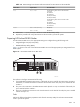
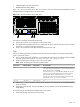
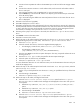
Figure 3-10 shows a rear view of the HP Integrity rx1620 server and the appropriate port assignments for
an HP XC system.
Figure 3-10 HP Integrity rx1620 Server Rear View
PCI-X 133
PCI-X 133
SCSI LVD/SE
LAN 10/100
LAN Gb A
GSP RESETS
SOFTHARD
LAN Gb B
CONSOLE / REMOTE / UPS
SERIAL
USB
The callouts on Figure 3-10 enumerate the following:
1. The port labeled LAN 10/100 is the MP connection to the ProCurve Console Switch.
2. The port labeled LAN Gb A connects to the Administration Switch (branch or root).
3. The port labeled LAN Gb B is used for an external connection.
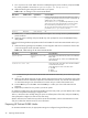
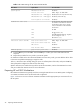
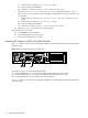
Figure 3-11 shows a rear view of the HP Integrity rx2600 server and the appropriate port assignments for
an HP XC system.
The high-speed interconnect card such as an InfiniBand or QsNet
II
card must be inserted into the top PCI-X
slot. The external connection is made on the Ethernet adapter card.
Figure 3-11 HP Integrity rx2600 Server Rear View
VGACONSOLE / REMOTE / UPS
LAN 10/100
LAN Gb
SCSI LVD/SE
USB
CONSOLE
SERIAL A
SERIAL B
PWR
1
PWR
2
Management Card
LAN 10/100
GSP RESETS
SOFTH ARD
TOC
PCI-X 133
PCI-X 133
PCI-X 133
PCI-X 133
The callouts on Figure 3-11 enumerate the following:
1. The top port labeled LAN 10/100 is the MP connection to the ProCurve Console Switch.
2. The port labeled LAN Gb connects to the Administration Switch (branch or root).
3. The bottom port labeled LAN 10/100 is unused.
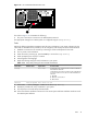
Tasks
Perform the following hardware preparation tasks on each HP Integrity server model rx1620 and rx2600
in your CP6000 system:
1. For each node in the HP XC system, ensure that the power cord is connected but that the CPU is not
turned on.
2. Follow this procedure to connect a personal computer (PC) to the Management Processor:
48 Preparing Individual Nodes