
HP XC System Software Hardware Preparation Guide Version 3.0
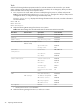
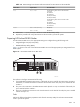
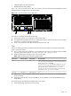
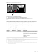
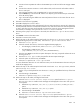

Table 3-9 BIOS Settings From the Boot and Power Menus for HP ProLiant DL145 G2 Nodes
Set To This ValueOption NameMenu Name
Set the following boot order on the head node:Boot orderBoot
1. Remote
2. CD-ROM
3. Hard Drive
4. PXE (slot 0200)
5. PXE (slot 0300)
Set the following boot order on all other nodes:
1. Remote
2. CD-ROM
3. PXE (slot 0300)
4. Hard Drive
DisabledWake On Modem RingPower
DisabledWake On LAN
4. Select Exit -> Save Changes and Exit to exit the BIOS Setup Utility.
5. Repeat this procedure for every HP ProLiant DL145 G2 node in your HP XC system.
Preparing HP ProLiant DL385 Nodes
On HP ProLiant DL385 servers, the appropriate settings are configured using the following tools:
• Integrated Lights Out (iLO) Setup Utility
• ROM-Based Setup Utility (RBSU)
Figure 3-7 shows a rear view of the HP ProLiant DL385 server and the appropriate port assignments for an
HP XC system.
Figure 3-7 HP ProLiant DL385 Server Rear View
3
1
2
HPTC-0145
3
1 3 3
M H z
1
100
M H z
2
1 0 0
M H z
The callouts on the figure enumerate the following:
1. If a Gigabit Ethernet (GigE) interconnect is configured, this port is used for the interconnect connection.
Otherwise, it is used for an external connection. On the back of the node, this port is marked with the
number 2.
2. This port is the connection to the Administration Switch (branch or root). On the back of the node, this
port is marked with the number 1.
3. This port is the Ethernet connection to the Console Switch. On the back of the node, this port is marked
with the acronym iLO.
Tasks
Perform the following hardware preparation tasks from the iLO Setup Utility for each HP ProLiant DL385
node in your HP XC system:
Tasks 43