
HP XC System Software Hardware Preparation Guide Version 3.0
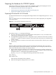
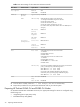
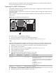

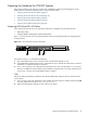
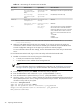

Figure 3-2 shows a rear view of the HP ProLiant DL360 G4 server and the appropriate port assignments
for an HP XC system.
Figure 3-2 HP ProLiant DL360 G4 Server Rear View
11
The callouts on Figure 3-2 enumerate the following:
1. The iLO Ethernet is the port used as the connection to the Console Switch.
2. NIC1 is used as the connection to the Administration Switch (branch or root).
3. NIC2 is used as the external connection.
Figure 3-3 shows a rear view of the HP ProLiant DL380 G4 server and the appropriate port assignments
for an HP XC system.
Figure 3-3 HP ProLiant DL380 G4 Server Rear View
3
2
SCSI Port 1
iL
O
2 1
UID
PCI-X
3
10
0
MH
z
2
10
0
MH
z
1
133
MH
z
PC
I-E
2
x4
1
x4
N/A
The callouts on Figure 3-3 enumerate the following:
1. The iLO Ethernet port is used as the connection to the Console Switch.
2. NIC2 is used as an external connection.
3. NIC1 is used as the connection to the Administration Switch (branch or root).
Tasks
Perform the following hardware preparation tasks from the iLO Setup Utility for each node in your HP XC
system:
1. Turn on power to the node. Watch the screen carefully during the power-on self-test, and press the F8
key when prompted to access the Integrated Lights Out Setup Utility.
2. Make the following iLO settings for each node in your system:
Tasks 35