
HP XC System Software Hardware Preparation Guide Version 3.0


affects the naming of the nodes in the system. The documentation that came with your interconnect hardware
can help you find this number.
Note
You may choose a number smaller than the absolute maximum number of interconnect ports for max-node,
but you can not expand the system to a size larger than this number in the future without completely
rediscovering the system, thereby renumbering all nodes in the system.
Specific considerations for connections to the interconnect based on interconnect type are discussed in the
following sections:
• QSnetII Interconnect Connections (page 28)
• Gigabit Ethernet Interconnect Connections (page 28)
• Administration Network Interconnect Connections (page 29)
• Other Types of Interconnect Connections (page 29)
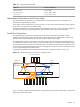
The method for wiring the Administration network and interconnect networks allows expansion of the system
within the system's initial interconnect fabric without recabling of any existing nodes. If additional switch
chassis or ports are added to the system as part of the expansion, some recabling may be necessary.
QSnet
II
Interconnect Connections
When the QSnet
II
interconnect developed by Quadrics is used, it is important that the nodes be connected
to the Quadrics switch ports in a specific order. The order is affected by the order of the Administration
Network and Console Network.
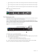
Because the Quadrics port numbers start numbering at 0, the highest port number on the Quadrics switch
is port max-node minus 1, where max-node is the maximum number of nodes possible in the system. This
is the port on the Quadrics switch to which the head node must be connected.
The head node is always the node connected to the highest port number of any node on the Root
Administration Switch and the Root Console Switch.
Note
The head node port is not the highest port number on the Root Administration Switch. Other higher port
numbers are used to connect to other switches. If the Root Administration Switch is a ProCurve 2848 switch,
the head node is connected to port number 42, as discussed in “Root Administration Switch ” (page 23).
If the Root Administration Switch is a ProCurve 2824 switch, the head node is connected to port number 22
on that switch, as discussed in “Root Administration Switch ” (page 23). The head node should, however,
be connected to the highest port number on the interconnect switch.
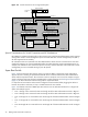
The next node connected directly to the root switches (Administration and Console) should have connections
to the Quadrics switch at the next highest port number on the Quadrics switch (max-node minus 2). All
nodes connected to the Root Administration Switch will be connected to the next port in descending order.
Nodes attached to branch switches must be connected starting at the opposite end of the Quadrics switch.
The node attached to the first port of the first Branch Administration Switch should be attached to the first
port on the Quadrics switch (Port 0).
Gigabit Ethernet Interconnect Connections
The HP XC System Software is not concerned with the topology of the Gigabit Ethernet interconnect, but it
makes sense to structure it in parallel with the System Administration network in order to make your connections
easy to maintain.
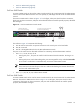
Because the first logical Gigabit Ethernet port on each node is always used for connectivity to the
Administration network, there must be a second Gigabit Ethernet port on each node if you are using Gigabit
Ethernet as the interconnect.
This may be a built-in port, as with the HP ProLiant DL145 server, the HP ProLiant DL585 server, the HP
ProLiant DL360 G4 and DL380 G4 servers, and the HP Integrity rx1620, rx2620, and rx4640 servers; or
28 Making Node and Switch Connections