
HP XC System Software Hardware Preparation Guide Version 3.0
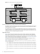

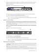


The ProCurve 2824 switch is shown in Figure 2-10. In the figure, white ports should not have connections,
black ports can have connections, and ports with numbered callouts are used for a specific purposes,
described after the figure.
Figure 2-10 ProCurve 2824 Branch Administration Switch
Pow e
r
Fault
hp procurve
switch 2824
J4903A
Lnk
Ac
t
FD
x
Sp
d
St
atus
RP
S
Fa
n
Te
st
LE
D
Mode
Cons ole
Reset Clear
T T T TM M M M
1
2
3
4
5
6
7
8
17
18
19
20
9
10
11
12
13
14
15
16
21 22 23 24
T
M
T
M
T
M
T
M
10/100/1000 Base-TX RJ-45 Ports
Dual Personality Ports
The callout in Figure 2-10, “ProCurve 2824 Branch Administration Switch” enumerates the following:
1. Port 22 is used for the link to the Root Administration Switch.
The ports on this switch must be allocated as follows for maximum performance:
• Ports 1–10 and 13–21 are used for the administration ports for the individual nodes (up to 19 nodes).
• Ports 11, 12, 23, and 24 are unused.
Branch Console Switches
The Branch Console Switch of an HP XC system is a ProCurve 2650 switch. The connections to the ports
must parallel the connections of the corresponding Branch Administration Switch. If a particular node uses
port N on a Branch Administration Switch, its management console port must be connected to port N on the
corresponding Branch Console Switch.
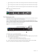
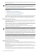
Figure 2-11 shows the ProCurve 2650 switch. In the figure, white ports should not have connections, black
ports can have connections, and ports with numbered callouts are used for a specific purpose, described
after the figure.
Figure 2-11 ProCurve 2650 Branch Console Switch
Po rt
LED
Vi
ew
Sel
f
Te
st
Cl
ea r
Re
se t
Fa
n
Statu
s
4
5
48
47
46
4543
4442
41
40
39
38
37
36
35
34
33
32
31
30
29
28
27
26
25
24
23
22
21
20
19
18
17
16
15
14
13
12
11
10
9
8
7
6
Spd m ode : off = 1 0 M bp s, fla s h = 1 0 0 Mbps , o n = 10 0 0 Mbps
10/100 Ba se
-T X P ort s ( 1 - 48)
Gi
g- T
Po
rts
Mi
ni -
GB
IC
Po rts
1 15 17
16
18
31
32
33
34
47
48
50
49
T
M
T
M
Po w er
Fa
ul t
hp pr oc ur ve
swi tc h
26 5 0
J4 8 9 9 A
Us
e o nl y o ne (T or M) f or e a ch G ig abit po r t
!
1
2
3
Spd
Ln k
Ac
t
FD x
10/100Base-TX RJ-45 Ports
Connections to Node Console Ports
Gigabit
Ethernet Ports
The callout in Figure 2-11 enumerates the following:
1. Port 50 is the link to the Root Console Switch.
The ports on this switch must be allocated as follows for maximum performance:
• Ports 1–10, 13–22, 25–34, 37–44 are used for the console ports of individual nodes (up to 38 nodes).
• Ports 11, 12, 23, 24, 35, 36, 45–49 are unused
Interconnect Connections
The high-speed interconnect connects every node in the HP XC system. Each node can have an interconnect
card installed in the highest speed PCI-X slot (133 Mhz). Check the hardware documentation to determine
which slot this is.
The interconnect switch console port (or monitoring line card) also connects to the Root Administration Switch
either directly or indirectly, as described in "Root Administration Switch " .
You must determine the absolute maximum number of nodes that could possibly be used with the interconnect
hardware that you have. This maximum number of ports on the interconnect switch or switches (max-node)
Interconnect Connections 27