
HP XC System Software Hardware Preparation Guide Version 3.0
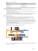

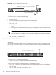


• Ports 29 through 32 are connected to Ports 43 through 46 of the Root Administration Switch in Region
6.
• Ports 37 through 40 are connected to Ports 43 through 46 of the Root Administration Switch in Region
7.
• Ports 41 through 44 are connected to Ports 43 through 46 of the Root Administration Switch in Region
8.
Figure 2-4 ProCurve 2848 Super Root Switch
LED
Mode
Cl
ea r
Re
se t
4
5 43
4442
41
40
39
38
37
36
35
34
33
32
31
30
29
28
27
26
25
24
23
22
21
20
19
18
17
16
15
14
13
12
11
10
9
8
7
6
Spd m ode : of f = 1 0 Mbps fla s h = 10 0 Mbps o n = 1 0 0 0 Mbps
1 15 17
16
18
31
32
33
34
Po w er
Fa
ul t
hp procurve
switch
2848
J4 904 A
Us
e o nl y o ne (T o r M) fo r e a ch G igabit port
!
1
2
3
Spd
Ln k
Ac
t
FD
x
10/100/1000 Base-TX RJ-45 Ports
Ports 1, 3, 5, and 7
are the first four ports
located on the top row
Gigabit
Ethernet Ports
48
47
T
M
T
M
46
45
T
M
T
M
RPS
Fan
Test
Ports 2, 4, 6, and 8
are the first four ports
located on the bottom row
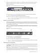
Root Administration Switch
The Root Administration Switch for the Administration Network of an HP XC system can be either a ProCurve
2848 switch or a ProCurve 2824 switch for small configurations.
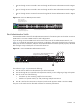
If you are using a ProCurve 2848 switch as the switch at the center of the Administration Network, use
Figure 2-5 to make the appropriate port connections. In the figure, white ports should not have connections,
black ports can have connections, and ports with numbered callouts are used for specific purposes, described
after the figure. Gray-colored ports are reserved for future use.
Figure 2-5 ProCurve 2848 Root Administration Switch
LED
Mode
Cl ear
Re set
4
5 43
4442
41
40
39
38
37
36
35
34
33
32
31
30
29
28
27
26
25
24
23
22
21
20
19
18
17
16
15
14
13
12
11
10
9
8
7
6
Spd m ode : of f = 1 0 Mbp s fl ash = 10 0 Mbps on = 1 00 0 Mbps
1 15 17
16
18
31
32
33
34
Po w er
Fa ul t
hp procurve
switch
2848
J4904A
Use o nly one (T o r M) fo r e ach Gigabit port
!
1
2
3
Sp d
Lnk
Ac t
FD x
48
47
T
M
T
M
46
45
T
M
T
M
RPS
Fan
Test
3
4
2
Gigabit Ethernet
Ports
10/100/1000 Base-TX RJ-45 Ports
Connections to Node Administration Ports
Begin at Port 41 (Descending)
Uplinks from Branches
Begin at Port 1 (Ascending)
The callouts in Figure 2-5 enumerate the following:
1. Port 42 must be used for the administration port of the head node.
2. Ports 43 through 46 are connected to the Super Root Switch if you are configuring a large-scale system.
3. Port 47 can be one of the following:
• Connection (or line monitoring card) for the interconnect
• Interlink to a separate switch (10/100) containing multiple interconnects
4. Port 48 is used as the interconnect to the Root Console Switch (ProCurve 2650 or ProCurve 2626)
The ports on this switch must be allocated as follows for maximum performance:
Switches 23