
HP XC System Software Hardware Preparation Guide Version 3.0
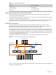
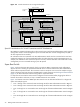
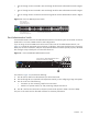

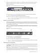
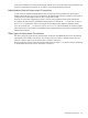


Figure 2-3 Switch Connections For a Large-Scale System
Super Root
Switch
ProCurve 2848
1 2 46
48
Ports 3 - 45
ProCurve 2848
ProCurve 2848
1 2 46
48
Ports 3 - 45
ProCurve 2650
ProCurve 2650
1 2 48
50
Ports 3 - 47
1 2 46
48
Ports 3 - 45
1 2 48
50
Ports 3 - 47
Ethernet
CP
Port
Node 1
Ethernet
CP
Port
Node 2
To Region 2
Root Admin
Switch
Branch Admin
Switch
Root Console
Switch
Branch Console
Switch
Region 1
To Next Switch To Next Switch
Special Considerations for Switch Connections and HP Workstations
HP xw8200 or xw9300 workstations do not have console ports. Only the Root Administration Switch supports
mixing nodes without console management ports with nodes that have console management ports (that is,
all other supported server models).
HP workstations that are connected to the Root Administration Switch must be connected to the next lower
numbered contiguous set of ports immediately before the nodes that have console management ports. For
example, the workstations are connected to ports 37 and 36, and the remainder of the nodes with console
management ports are connected starting at port 38 upward.
Super Root Switch
Figure 2-4 shows the Super Root Switch, which is a ProCurve 2848. A Super Root switch configuration
supports the use of trunking to expand the bandwidth of the connection between the Root Administration
Switch and the Super Root Switch. The connection can be as simple as one wire and as complex as eight,
which is the largest trunk size the ProCurve 2848 switch currently supports. See Trunking and Switch Choices
(page 19) for more information about trunking and the Super Root Switch.
It is important to know that the trunks must be configured on
both
switches before plugging the cables in
between the switches. Otherwise, a loop is created between the two switches.
Figure 2-4 illustrates a ProCurve 2848 Super Root Switch. Ports are allocated as follows for a large-scale
system with multiple regions:
• Ports 1 through 4 are connected to Ports 43 through 46 of the Root Administration Switch in Region 1.
• Ports 5 through 8 are connected to Ports 43 through 46 of the Root Administration Switch in Region 2.
• Ports 13 through 16 are connected to Ports 43 through 46 of the Root Administration Switch in Region
3.
• Ports 17 through 20 are connected to Ports 43 through 46 of the Root Administration Switch in Region
4.
• Ports 25 through 28 are connected to Ports 43 through 46 of the Root Administration Switch in Region
5.
22 Making Node and Switch Connections