HP XC System Software Hardware Preparation Guide Version 3.
© Copyright 2003, 2004, 2005, 2006 Hewlett-Packard Development Company, L.P. The information contained herein is subject to change without notice. The only warranties for HP products and services are set forth in the express warranty statements accompanying such products and services. Nothing herein should be construed as constituting an additional warranty. HP shall not be liable for technical or editorial errors or omissions contained herein.
Table of Contents About This Document.....................................................................................9 Intended Audience..................................................................................................................................9 Document Organization...........................................................................................................................9 HP XC Information............................................................................
Preparing HP ProLiant DL385 Nodes..................................................................................................43 Preparing HP ProLiant DL585 Nodes..................................................................................................44 Preparing HP xw9300 Workstations...................................................................................................46 Preparing the Hardware for CP6000 Systems.....................................................................
List of Figures 1-1 Administration Network: Console Branch................................................................................................17 2-1 Application and Utility Cabinets............................................................................................................19 2-2 Node and Switch Connections on a Typical System..................................................................................21 2-3 Switch Connections For a Large-Scale System.........................
List of Tables 1-1 Supported Server Models.....................................................................................................................15 1-2 Supported Interconnects........................................................................................................................16 1-3 Supported Console Management Devices...............................................................................................16 2-1 Supported Switch Models...................................
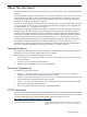
About This Document This document describes how to prepare the nodes in your HP cluster platform before installing HP XC System Software. An HP XC system is integrated with several open source software components. Some open source software components are being used for underlying technology, and their deployment is transparent. Some open source software components require user-level documentation specific to HP XC systems, and that kind of information is included in this document, if required.
HP XC Hardware Preparation Guide Describes tasks specific to HP XC that are required to prepare each supported cluster platform for installation and configuration, including required node and switch connections. HP XC System Software Installation Guide Provides step-by-step instructions for installing the HP XC System Software on the head node and configuring the system.
The location of each Web site or link to a particular topic listed in this section is subject to change without notice by the site provider. • http://www.platform.com Home page for Platform Computing Corporation, the developer of the Load Sharing Facility (LSF). LSF HPC with SLURM, the batch system resource manager used on an HP XC system, is tightly integrated with the HP XC and SLURM software. Standard LSF is also available as an alternative.
• http://www.etnus.com Home page for Etnus, Inc., maker of the TotalView® parallel debugger. • http://www.macrovision.com Home page for Macrovision®, developer of the FLEXlm™ license management utility, which is used for HP XC license management. • http://sourceforge.net/projects/modules/ Home page for Modules, which provide for easy dynamic modification of a user's environment through modulefiles, which typically instruct the module command to alter or set shell environment variables. • http://dev.
• http://linuxvirtualserver.org Home page for the Linux Virtual Server (LVS), the load balancer running on the Linux operating system that distributes login requests on the HP XC system. • http://www.gnu.org Home page for the GNU Project. This site provides online software and information for many programs and utilities that are commonly used on GNU/Linux systems. Online information include guides for using the bash shell, emacs, make, cc, gdb, and more. Related MPI Web Sites • http://www.mpi-forum.
ENVIRONMENT VARIABLE ERROR NAME Key Term User input Variable [] {} ... | WARNING CAUTION IMPORTANT NOTE The name of an environment variable, for example, PATH. The name of an error, usually returned in the errno variable. The name of a keyboard key. Return and Enter both refer to the same key. The defined use of an important word or phrase. Commands and other text that you type. The name of a placeholder in a command, function, or other syntax display that you replace with an actual value.
1 Hardware and Network Overview The following topics are addressed: • Supported Cluster Platforms (page 15) • Interconnect Network (page 15) • Supported Console Management Devices (page 16) • Administration Network (page 16) • Administration Network: Console Branch (page 17) • Large-Scale Systems (page 17) Supported Cluster Platforms The hardware supported in the HP XC system is the HP Cluster Platform 3000 (CP3000), HP Cluster 4000 (CP4000), and HP Cluster Platform 6000 (CP6000).
Table 1-2 Supported Interconnects Cluster Platform Gigabit Ethernet InfiniBand® Myrinet® CP3000 X X (PCIX and PCI Express) X CP4000 X X (PCIX) X CP6000 X X QsNetII® X X The Myrinet adapters can be either the single-port M3F-PCIXD-2 (Rev. D) or the dual port M3F2–PCIXE-2 (Rev. E). All adapters must be of one type only; a mix of both types of adapters is not supported. The QsNetII high-speed interconnect from Quadrics, Ltd. is the only version of Quadrics interconnects that is supported.
possible configuration choices. The main system administration branch of the network uses a Gigabit Ethernet interconnect. The Administration Network has at least one Root Administration Switch and can have multiple Branch Administration Switches. These switches are discussed in "Switches" .
2 Making Node and Switch Connections This chapter provides information about the connections between nodes and switches that are required for an HP XC system. The following topics are addressed: • Cabinets (page 19) • Trunking and Switch Choices (page 19) • Switches (page 20) • Interconnect Connections (page 27) Cabinets Two types of cabinets contain the HP XC system hardware: • Utility cabinet • Application cabinet Cabinets are used as a packaging medium.
For physically larger platforms (2U and larger) such the HP Integrity rx2600 and HP ProLiant DL585 servers, a smaller number of servers can be placed in a single cabinet. In this case, the branch switch is a ProCurve Switch 2824, which is sufficient to support up to 19 nodes. In this release, the HP XC System Software supports the use of one-wire connections or two-wire trunks between the Root Administration Switches and the Branch Administration Switches.
Table 2-1 Supported Switch Models Switch Use ProCurve Switch Model Super Root Switch ProCurve 2848 Administration Switch ProCurve 2848 or 2824 Console Switch ProCurve 2650 or 2626 Administrator Passwords on a ProCurve Switch The documentation that came with your model of ProCurve switch describes how to optionally set an administrator's password for the switch.
Figure 2-3 Switch Connections For a Large-Scale System ProCurve 2848 Super Root Switch 1 2 Ports 3 - 45 46 48 To Region 2 ProCurve 2650 ProCurve 2848 Root Admin Switch 1 2 Ports 3 - 45 46 48 1 2 To Next Switch 1 2 Ports 3 - 45 Ethernet Root Console Switch ProCurve 2650 46 48 CP Port Node 1 48 50 To Next Switch ProCurve 2848 Branch Admin Switch Ports 3 - 47 1 2 Ports 3 - 47 Ethernet 48 50 Branch Console Switch CP Port Node 2 Region 1 Special Considerations for Switch Conne
• Ports 29 through 32 are connected to Ports 43 through 46 of the Root Administration Switch in Region 6. • Ports 37 through 40 are connected to Ports 43 through 46 of the Root Administration Switch in Region 7. • Ports 41 through 44 are connected to Ports 43 through 46 of the Root Administration Switch in Region 8.
• Ports 1–10, 13–22, 25–34, 37–42 • Starting with port 1, the ports are used for links from Branch Administration Switches, which includes the use of trunking. Two-port trunking can be used for each Branch Administration Switch. NOTE Trunking is restricted to within the same group of 10 (you cannot trunk with ports 10 and 13). HP recommends that all trunking use consecutive ports within the same group (1–10, 13–22, 25–34, or 37–42).
• ProCurve 2650 Switch (page 25) • ProCurve 2626 Switch (page 25) ProCurve 2650 Switch A ProCurve 2650 switch can be used as a Root Console Switch for the Console Branch of the Administration network. The Console Branch functions at a lower speed (10/100 Mbps) than the rest of the Administration network. The ProCurve 2650 switch is shown in Figure 2-7.
Figure 2-8 ProCurve 2626 Root Console Switch Uplinks from Branches Start at port 1 (Ascending) hp procurve switch 2626 J4900A Self Te st Power Fan Status LED Mode Connections to Node Console Ports Start at port 21 (Descending) 2 1 3 4 5 6 8 7 9 10 11 12 13 14 15 16 17 18 19 20 21 22 23 24 Gig-T Ports T Lnk 25 M T 26 M Ac t MiniGBIC Ports FDx Spd Faul t Reset Clear Spd Mode off = 10Mbps flash = 100Mbps Use only one (T or M) for Gigabit port on = 1000Mbps Gigabit Ethernet Por
The ProCurve 2824 switch is shown in Figure 2-10. In the figure, white ports should not have connections, black ports can have connections, and ports with numbered callouts are used for a specific purposes, described after the figure.
affects the naming of the nodes in the system. The documentation that came with your interconnect hardware can help you find this number. Note You may choose a number smaller than the absolute maximum number of interconnect ports for max-node, but you can not expand the system to a size larger than this number in the future without completely rediscovering the system, thereby renumbering all nodes in the system.
it may be an installed card, as with the HP Integrity rx2600 server. Any node with an external interface must also have a third Ethernet connection of any kind to communicate with external networks. Administration Network Interconnect Connections In cases where an additional Gigabit Ethernet port or switch may not be available, the HP XC System Software allows the interconnect to be configured on the Administration Network.
3 Preparing Individual Nodes This chapter contains information about preparing the nodes in your HP Cluster Platform to prepare for the HP XC software installation.
Ethernet Port Connections on the Head Node Table 3-2 lists the Ethernet port connections on the head node based on the type of interconnect in use. Use this information to determine the appropriate connections to make for the external network connection on the head node. Table 3-2 Ethernet Ports on the Head Node Gigabit Ethernet Interconnect All Other Interconnect Types 1. Physical onboard Port #1 is always the connection to the 1.
Preparing the Hardware for CP3000 Systems Follow the procedures in this section to prepare each node before installing and configuring the HP XC System Software.
Table 3-3 BIOS Settings for the HP ProLiant DL140 G2 Nodes Menu Name Submenu Name Boot Options Advanced Option Name Set To This Value Numlock Off MCFG Table Disabled Advanced Options Hyperthreading Disabled IPMI LAN Settings Make the following settings on the head node: 1. Change the IP Address assignment to Static 2. Enter the local IP address 3. Enter the netmask for your site 4.
Figure 3-2 shows a rear view of the HP ProLiant DL360 G4 server and the appropriate port assignments for an HP XC system. Figure 3-2 HP ProLiant DL360 G4 Server Rear View 1 The 1. 2. 3. callouts on Figure 3-2 enumerate the following: The iLO Ethernet is the port used as the connection to the Console Switch. NIC1 is used as the connection to the Administration Switch (branch or root). NIC2 is used as the external connection.
Table 3-4 iLO Settings for HP ProLiant DL360 G4 and DL380 G4 Nodes Menu Name SubMenu Name User Option Name Set To This Value Add Create a common iLO user name and password for every node in your system. The password must have a minimum of 8 characters by default, but this value is configurable. The user Administrator is predefined by default, but you must create your own user name and password. For security purposes, HP recommends that you delete the Administrator user.
Specific instructions are outside the scope of the HP XC documentation; see the documentation that came with your model of HP ProLiant server for more information. Preparing HP xw8200 Workstations HP xw8200 workstations can be integrated into an HP XC system. Configuring an xw8200 workstation as the HP XC head node is supported. Follow the procedures in this section to prepare each workstation before installing and configuring the HP XC System Software.
9. Turn off power to all nodes except the head node. 10. Follow the software installation instructions in the HP XC System Software Installation Guide to install the HP XC System Software.
Preparing the Hardware for CP4000 Systems Follow the procedures in this section to prepare each node before installing and configuring the HP XC System Software.
Table 3-7 BIOS Settings for HP ProLiant DL145 Nodes Menu Name Submenu Name Option Name Set To This Value Boot Boot Settings Configuration (for NIC1) Onboard NIC PXE Option ROM Enabled (for all nodes except the head node) Boot Settings Configuration (for NIC1) Onboard NIC PXE Option ROM Disabled (for the head node) Advanced Management Processor Set Serial Port Configuration Sharing Shared BIOS Serial Console Configuration Redirection After BIOS Post Enabled Boot Device Priority1 Set the hea
6. Ensure that all machines are requesting IP addresses through the Dynamic Host Control Protocol (DHCP). Do the following to determine if DHCP is enabled: a. At the ProLiant> prompt, enter the following: ProLiant> net b. At the INET> prompt, enter the following: INET> state iface...ipsrc.....IP addr........subnet.......gateway 1-et1 dhcp 0.0.0.0 255.0.0.0 0.0.0.0 current tick count 2433 ping delay time: 280 ms. ping host: 0.0.0.0 Task wakeups:netmain: 93 nettick: 4814 telnetsrv: 401 c.
Tasks Perform the following hardware preparation tasks for each HP ProLiant DL145 G2 node in your HP XC system. Change only the values that are described in this procedure; do not change any factory-set values unless instructed. Follow all steps in the sequence shown: 1. Turn on power to the node. Watch the screen carefully during the power-on, self-test, and press the F10 key when prompted to access the BIOS Setup Utility.
Table 3-9 BIOS Settings From the Boot and Power Menus for HP ProLiant DL145 G2 Nodes Menu Name Option Name Set To This Value Boot Boot order Set the following boot order on the head node: 1. Remote 2. CD-ROM 3. Hard Drive 4. PXE (slot 0200) 5. PXE (slot 0300) Set the following boot order on all other nodes: 1. Remote 2. CD-ROM 3. PXE (slot 0300) 4. Hard Drive Power 4. 5. Wake On Modem Ring Disabled Wake On LAN Disabled Select Exit -> Save Changes and Exit to exit the BIOS Setup Utility.
1. 2. Turn on power to the node. Watch the screen carefully during the power-on self-test, and press the F8 key when prompted to access the Integrated Lights Out Setup Utility. Make the following iLO settings for each node in your system: Table 3-10 iLO Settings for HP ProLiant DL385 Nodes Menu Name SubMenu Name User Option Name Set To This Value Add Create a common iLO user name and password for every node in your system.
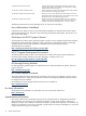
• Integrated Lights Out (iLO) Setup Utility • ROM-Based Setup Utility (RBSU) Figure 3-8, “HP ProLiant DL585 Server Rear View” shows a rear view of the HP ProLiant DL585 server and the appropriate port assignments for an HP XC system. Figure 3-8 HP ProLiant DL585 Server Rear View PCI -X 64- B it 100M Hz 8 7 6 5 4 3 2 1 133M Hz 2 1 iL O 2 ! 1 2 1 UID The callouts on the figure enumerate the following: 1. The iLO Ethernet port is the connection to the Console Switch. 2.
Table 3-13 RBSU Settings for HP ProLiant DL585 Nodes Menu Name Option Name Set To This Value System Options Embedded Serial Port Disabled Virtual Serial Port COM1; IRQ4; IO:3F8h-3FFh Embedded NIC Port 1 PXE Support Enabled (all nodes except the head node) Embedded NIC Port 1 PXE Support Disabled ( head node only) Power Regulator for ProLiant Disabled On the head node, set the boot order so that the CD-ROM is listed before the hard disk.
Figure 3-9 HP xw9300 Workstation Rear View 1 The callout in Figure 3-9 enumerates the following: 1. This port is used as the connection to the Administration Network. The appropriate settings for an HP XC system are configured using the Setup Utility. Tasks Perform the following hardware preparation tasks for every workstation in your system. Change only the values that are described in this procedure; do not change any other factory-set values unless instructed: 1.
Preparing the Hardware for CP6000 Systems Follow the procedures in this section to prepare your model of HP Integrity server before installing and configuring the HP XC System Software.
a. b. c. d. e. 3. 4. 5. 6. 7. 8. 9. Connect a three-way DB9–25 cable to the MP DB-25 port on the back of the HP Integrity rx2600 server. Connect the CONSOLE connector to a null modem cable, and connect the null modem cable to the PC COM1 port. Use a terminal emulator, such as HyperTerminal, to open a terminal window. Press the Enter key to access the MP. If there is no response, press the MP reset pin on the back of the MP and try again.
i. ii. iii. Enable the Acpi(HWP0002,700)/Pci(2|0) option. Save the setting to the NVRAM. Select Exit to return to the Boot Option Maintenance Menu. c. Select the Select Active Standard Error Devices option from the Boot Option Maintenance Menu to enable console messages to be displayed on the screen when you turn on the system. i. Enable the Acpi(HWP0002,700)/Pci(1|1)/Uart(9600 N81)/VenMsg(Vt100+) option. ii. Enable the Acpi(HWP0002,700)/Pci(2|0) option. iii. Save the setting to the NVRAM. iv.
Figure 3-13 HP Integrity rx4640 Server Rear View 1 The 1. 2. 3. 2 3 HPTC-0146 callouts on Figure 3-13 enumerate the following: The port labeled MP LAN is the MP connection to the ProCurve Console Switch. The port labeled LAN Gb connects to the Administration Switch (branch or root). This unlabeled port is used for an external connection. Tasks Perform the following hardware preparation tasks on each HP Integrity rx2620 and rx4640 server in your HP XC system: 1. 2. 3. 4. 5. 6. 7. 8. 9.
e. f. Enter Y to save the entry to NVRAM. Select Exit to quit. For more information about how to work with these menus, see the documentation that came with your model of HP Integrity server. 10. Perform this step on all nodes except the head node. From the Boot Configuration screen, select the option to Edit OS Boot Order: a. Use the navigation instructions on the screen to move the Netboot entry you just defined to the top of the boot order. b. Enter Y to save the entry to NVRAM. c.
Appendix A Establishing a Connection Through a Serial Port Follow this generic procedure to establish a connection to a server using a serial port connection to a console port. If you need more information about how to establish these connections, see the documentation that came with your model of HP server. 1. Connect a null modem cable between the serial port on the rear panel of the server and a COM port on the host computer. 2. Verify that the serial port is configured to Shared. 3.
Glossary A administration branch The half (branch) of the administration network that contains all of the general-purpose administration ports to the nodes of the HP XC system. administration network The private network within the HP XC system that is used for administrative operations. B base image The collection of files and directories that represents the common files and configuration data that are applied to all nodes in an HP XC system. branch switch A component of the Administration Network.
FCFS First-come, first-served. An LSF job-scheduling policy that specifies that jobs are dispatched according to their order in a queue, which is determined by job priority, not by order of submission to the queue. first-come, first-served See FCFS. G global storage Storage within the HP XC system that is available to all of the nodes in the system. Also known as local storage. golden client The node from which a standard file system image is created.
L Linux Virtual Server See LVS. load file A file containing the names of multiple executables that are to be launched simultaneously by a single command. Load Sharing Facility See LSF-HPC with SLURM. local storage Storage that is available or accessible from one node in the HP XC system. LSF execution host The node on which LSF runs. A user's job is submitted to the LSF execution host. Jobs are launched from the LSF execution host and are executed on one or more compute nodes.
Network Information Services See NIS. NIS Network Information Services. A mechanism that enables centralization of common data that is pertinent across multiple machines in a network. The data is collected in a domain, within which it is accessible and relevant. The most common use of NIS is to maintain user account information across a set of networked hosts. NIS client Any system that queries NIS servers for NIS database information.
SMP Symmetric multiprocessing. A system with two or more CPUs that share equal (symmetric) access to all of the facilities of a computer system, such as the memory and I/O subsystems. In an HP XC system, the use of SMP technology increases the number of CPUs (amount of computational power) available per unit of space. ssh Secure Shell. A shell program for logging in to and executing commands on a remote computer.
Index A administration network as interconnect, 29 B baseboard management controller (see BMC) BIOS settings CP4000 systems, 36, 44 BMC, 16 BMC firmware, 31 branch administration switch, 20, 26 branch console switch, 20, 27 C cabinets, 19 console management devices, 16 D DHCP, 41 discovery, 32 E EFI boot manager CP6000 systems, 49 EFI firmware, 31 ELAN4 (see Quadrics) Ethernet ports head node, 32 external storage, 19 F firmware BMC, 31 EFI FW, 31 InfiniBand, 31 IPMI, 31 list, 31 MP, 31 Myrinet, 31 Quad
system administration, 16 system administration console branch, 17 node head, 19 nodes maximum number of, 27 P password iLO, 35, 44–45 MP, 49, 51 ProCurve switch administrator, 21 PCI-X, 27 port connections branch administration switch, 26 branch console switch, 27 interconnect switch, 27 root administration switch, 23 root console switch, 24 super root switch, 22 pre-boot execution environment (see PXE) processor architecture, 15 ProCurve 2626, 20 ProCurve 2650, 20 branch console switch, 27 root console s