HP XC Systems with HP Server Blades and Enclosures HowTo Version 3.1 or Version 3.
© Copyright 2006, 2007 Hewlett-Packard Development Company, L.P. Confidential computer software. Valid license from HP required for possession, use or copying. Consistent with FAR 12.211 and 12.212, Commercial Computer Software, Computer Software Documentation, and Technical Data for Commercial Items are licensed to the U.S. Government under vendor's standard commercial license. The information contained herein is subject to change without notice.
Table of Contents 1 Overview.........................................................................................................................9 1.1 Minimum Requirements...................................................................................................................9 1.2 Read the Documentation Before You Begin......................................................................................9 1.3 Supported Server Blade Combinations..................................................
6 Making Node-Specific Settings..................................................................................33 6.1 Making Settings on Non-Blade Servers...........................................................................................33 6.2 Making Settings on HP ProLiant Server Blades..............................................................................33 6.3 Making Settings on HP Integrity Server Blades..............................................................................
List of Figures 3-1 3-2 3-3 3-4 3-5 3-6 3-7 A-1 A-2 A-3 Administration Network Connections..........................................................................................16 Console Network Connections......................................................................................................17 Gigabit Ethernet Interconnect Connections..................................................................................18 InfiniBand Interconnect Connections...................................
List of Tables 1-1 2-1 4-1 4-2 6-1 6-2 6-3 7-1 Minimum Requirements.................................................................................................................9 Installation and Configuration Checklist......................................................................................13 Head Node Installation Instructions.............................................................................................23 Boot Command Line Options Based on Hardware Model....................
1 Overview HP Server Blade c-Class servers (hereafter called server blades) are perfectly suited to form HP XC systems. Physical characteristics make it possible to have many tightly interconnected nodes while at the same time reducing cabling requirements. Typically, server blades are used as compute nodes but they can also function as the head node and service nodes.
If you do not have the required documentation in your possession, see the following sources: • The most current documentation for HP Server Blades, enclosures, and other server blade components is available at the following Web site: http://www.hp.com/go/bladesystem/documentation • The most current edition of the Version 3.1 or Version 3.2 HP XC System Software Documentation Set is available at the following Web site: http://www.docs.hp.com/en/highperfcomp.
• HP ProLiant BL685c (full-height) — Up to four dual core Opteron processors — Four built-in NICs — Two hot plug drives — Three mezzanine slots • HP ProLiant BL860c (full-height) 1.4.2 Enclosures and Onboard Administrators HP Server Blade c7000 Enclosure The HP Server Blade c7000 Enclosure is the enclosure model supported for use in an HP XC hardware configuration. An enclosure is a chassis that houses and connects blade hardware components.
Onboard Administrator. On server blades, iLO2 advanced features are enabled by default and include the following: • • Full remote graphics console access including full keyboard, video, mouse (KVM) access through a Web browser Support for remote virtual media which enables you to mount a local CD or diskette and serve it to the server blade over the network 1.4.
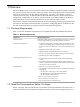
2 Task Summary and Checklist This chapter contains a summary of the steps required to configure HP server blades in an HP XC cluster. 2.1 Best Practice for System Configuration In order to function properly as an HP XC system, each component must be configured according to HP XC guidelines. To make configuration settings on certain components, an active network is required. However, on an HP XC system, the internal administration network is not operational until the head node is installed and running.
Table 2-1 Installation and Configuration Checklist (continued) Task Category Task Description Where Documented Run the discover --enclosurebased --network command on the head node to discover the switches Section 5.4 Set the Onboard Administrator password, which Section 5.
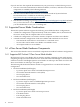
3 Cabling The following topics are addressed in this chapter: • • • • • “Network Overview ” (page 15) “Cabling for the Administration Network” (page 15) “Cabling for the Console Network” (page 16) “Cabling for the Interconnect Network” (page 17) “Cabling for the External Network” (page 19) 3.1 Network Overview An HP XC system consists of several networks: administration, console, interconnect, and external (public).
Figure 3-1 Administration Network Connections Non-Blade Server MGT NIC NIC PCI SLOT Non-Blade Server PCI SLOT MGT C-Class Blade Enclosure FULL HEIGHT BLADE NIC 1 NIC 2 NIC 3 NIC 4 MEZZ 1 MEZZ 2 MEZZ 3 HALF HEIGHT BLADE iLO2 NIC 1 NIC 2 MEZZ 1 MEZZ 2 iLO2 NIC NIC PCI SLOT PCI SLOT Admin ProCurve 2800 Series Switch Interconnect bay 1 Interconnect bay 2 Interconnect bay 3 Console ProCurve 2600 Series Switch Interconnect bay 4 Interconnect bay 5 Interconnect bay 6 Gigabit Ethernet Interconnect
Figure 3-2 Console Network Connections Non-Blade Server MGT NIC NIC PCI SLOT Non-Blade Server PCI SLOT MGT NIC C-Class Blade Enclosure NIC 1 NIC 2 NIC 3 NIC 4 MEZZ 1 MEZZ 2 MEZZ 3 iLO2 NIC 1 NIC 2 MEZZ 1 MEZZ 2 iLO2 PCI SLOT NIC PCI SLOT Admin ProCurve 2800 Series Switch Interconnect bay 1 Interconnect bay 2 Interconnect bay 3 Console ProCurve 2600 Series Switch Interconnect bay 4 Interconnect bay 5 Interconnect bay 6 Gigabit Ethernet Interconnect Switch Interconnect bay 7 Interconnect bay
Figure 3-3 Gigabit Ethernet Interconnect Connections Non-Blade Server MGT NIC NIC PCI SLOT Non-Blade Server PCI SLOT MGT NIC C-Class Blade Enclosure PCI SLOT NIC PCI SLOT Admin ProCurve 2800 Series Switch Interconnect bay 1 NIC 1 NIC 2 Interconnect bay 2 NIC 3 NIC 4 Console ProCurve 2600 Series Switch Interconnect bay 3 MEZZ 1 Interconnect bay 4 MEZZ 2 MEZZ 3 Interconnect bay 5 iLO2 Gigabit Ethernet Interconnect Switch Interconnect bay 6 NIC 1 Interconnect bay 7 NIC 2 Interconne
3.4.3 Configuring the Interconnect Network Over the Administration Network In cases where an additional Gigabit Ethernet port or switch may not be available, the HP XC System Software enables you to configure the interconnect on the administration network. When the interconnect is configured on the administration network, only a single LAN is used.
server blades do not have three NICs, and therefore, half-height server blades are not included in this example Because NIC1 and NIC3 on a full-height server blade are connected to interconnect bay 1, you must use VLANs on the switch in that bay to separate the external network from the administration network. Also, in this example, PCI Ethernet cards are used in the non-blade server nodes.
Figure 3-6 External Network Connections: Half-Height Server Blades and NIC1 and NIC2 in Use Non-Blade Server MGT NIC NIC PCI SLOT Non-Blade Server PCI SLOT MGT NIC NIC PCI SLOT PCI SLOT Ethernet PCI Cards C-Class Blade Enclosure FULL HEIGHT BLADE NIC 1 NIC 2 NIC 3 NIC 4 MEZZ 1 MEZZ 2 MEZZ 3 HALF HEIGHT BLADE iLO2 NIC 1 NIC 2 MEZZ 1 MEZZ 2 iLO2 Ethernet Mezzanine Cards Admin ProCurve 2800 Series Switch Interconnect bay 1 Interconnect bay 2 Interconnect bay 3 Console ProCurve 2600 Series Swi
Figure 3-7 External Network Connections: Half and Full-Height Server Blades and NIC1 in Use Non-Blade Server MGT NIC NIC PCI SLOT Non-Blade Server PCI SLOT MGT C-Class Blade Enclosure FULL HEIGHT BLADE NIC 1 NIC 2 NIC 3 NIC 4 MEZZ 1 MEZZ 2 MEZZ 3 HALF HEIGHT BLADE iLO2 NIC 1 NIC 2 MEZZ 1 MEZZ 2 iLO2 NIC NIC PCI SLOT PCI SLOT Admin ProCurve 2800 Series Switch Interconnect bay 1 Interconnect bay 2 Interconnect bay 3 Console ProCurve 2600 Series Switch Interconnect bay 4 Interconnect bay 5 Int
4 Installing HP XC System Software On the Head Node The information in this chapter parallels the information in Chapter 2 in the HP XC System Software Installation Guide. At some points, you might be instructed to refer to that document. Table 4-1 lists where to find head node installation instructions. The instructions differ if the head node is an HP server blade. Table 4-1 Head Node Installation Instructions Is the Head Node a Server Blade? Installation Procedure No 1.
1. 2. 3. 4. 5. To provide IP addresses for the Onboard Administrator and all iLO2 devices in the enclosure, disconnect the Onboard Administrator associated with the head node from the administration network, and plug the Onboard Administrator into an active network with a DHCP server. Obtain the IP address of the Onboard Administrator from the Insight Display panel on the enclosure.
1. 2. 3. 4. 5. Insert the HP XC System Software Version 3.1 or Version 3.2 DVD into the DVD drive of the local laptop or PC. Do the following from the Onboard Administrator management Web page: a. In the left frame, click the plus sign (+) to open the Device Bays menu. b. Click the plus sign (+) next to the node that represents the head node. c. Click on the link to the iLO to open the Integrated Lights-Out 2 Web utility.
8. See Table 2-5 in the HP XC System Software Installation Guide, which describes each installation prompt and provides information to help you with your answers. 9. When the HP XC software installation process is complete, log in as the root user. 10. Follow the instructions in Sections 2.4 and 2.5 in the HP XC System Software Installation Guide to install additional third-party software on the head node, if required.
5 Discovering the Hardware Components This chapter describes the following tasks, which you must complete in the order shown: • • • • • • “Task 1: Prepare for the System Configuration” (page 27) “Task 2: Change the Default IP Address Base (Optional)” (page 28) “Task 3: Use the cluster_prep Command to Prepare the System” (page 28) “Task 4: Discover Switches” (page 29) “Task 5: Set the Onboard Administrator Password” (page 30) “Task 6: Discover Enclosures and Nodes” (page 30) 5.
5.2 Task 2: Change the Default IP Address Base (Optional) You may need to change the default IP address base of the HP XC private networks if the default values conflict with another IP address base at your site. The IP address base is defined in the base_addrV2.ini file. Follow this optional procedure to change the default IP address base for the HP XC private networks: 1. 2. Begin this procedure as the root user on the head node.
on the head node, to start the MySQL service, and initialize the configuration and management database: 1. 2. Begin this procedure as the root user on the head node. Change to the following directory: # cd /opt/hptc/config/sbin 3. Start the system preparation process: # ./cluster_prep --enclosurebased 4. See Chapter 3, Task 3 in the HP XC System Software Installation Guide, which describes each cluster_prep prompt and provides information to help you with your answers.
Enter the MAC address of the switch the head node plugs into in the format xx:xx:xx:xx:xx:xx : your_MAC_address Please enter the Procurve switch Administrator password : your_password Please re-enter password: your_password Discovering Switches... Restarting dhcpd Waiting for IP addresses to stabilize .................... done discoverSwitches: IP: 172.31.32.1 name: blc1nxcsw000000000000-0 model: 2824 MaxPorts: 24 Checking switch 172.31.32.1 for neighboring switches ... done discoverSwitches: IP: 172.31.63.
1. Change to the following directory: # cd /opt/hptc/config/sbin 2. Discover all enclosures: # ./discover --enclosurebased --enclosures Discovery - XC Cluster version HP XC V3.1 RC2 20061022 Enter the common user name for all console port management devices: your_username Please enter the password for Administrator: your_password Please re-enter password: your_password Discovering blade enclosures ... Checking switch 172.31.32.2 for active ports ...done Getting MAC addresses from switch 172.31.32.2 ...
Starting CMF for discover... Stopping cmfd: [FAILED] Starting cmfd: [ OK ] Waiting for CMF to establish console connections .......... done 1 uploading database Restarting dhcpd Opening /etc/hosts Opening /etc/hosts.new.XC Opening /etc/powerd.conf Building /etc/powerd.conf ... done Attempting to start hpls power daemon ... done Waiting for power daemon ... done uploading database 1 32 The discover command turns off the console management facility (CMF) daemon.
6 Making Node-Specific Settings Running the discover process has assigned IP addresses to all hardware components. You can now use the active administration network to access the various hardware components to make node-specific BIOS settings that are required for HP XC. IMPORTANT: Making the required settings on each node is a key element in the successful installation and configuration of the system.
6. 7. 8. In the left frame, click the plus sign (+) next to Device Bays to display the list of nodes contained in the enclosure. Click the link to the first hardware model in the list. Wait a few seconds until the frame to the right is populated with node-specific information. Click the Boot Options tab. a. Select a boot device, and use the up and down arrows on the screen to position the device so that it matches the boot order listed in Table 6-1. Table 6-1 Boot Order for HP ProLiant Server Blades b. 9.
e. Click the Apply button to save the settings. 12. Configure disks into the smart array from the remote graphics console. All server blades have smart array cards, you must add the disk or disks to the smart array before attempting to image the node. To set up the smart array device, click the Remote Console tab on the virtual console page of the iLO2 Web Administration Utility, and then do one of the following depending on the browser type.
16. Close the iLO2 utility Web page. 17. Repeat this procedure from every active Onboard Administrator and make the same settings for each server blade in each enclosure. 6.
9. Enter UC (user configuration) and use the menu options to remove the default administrator and operator accounts. Then, for security purposes, create your own unique user login ID and password. Assign all rights (privileges) to this new user. The user login ID must have a minimum of 6 characters, and the password must have exactly 8 characters. You must set the same user login ID and password on every node and all MPs, iLOs, and OAs must use the same user name and password.
15. Turn off power to the node: a. Press Ctrl+b to exit the console mode. b. Return to the Command Menu: MP> CM c. Turn off power to the node: MP:CM> pc -off -nc 16. Use the RB command to reset the BMC. 17. Press Ctrl+b to exit the console mode and press the x key to exit.
7 Configuring the HP XC System The information in this chapter parallels the information in Chapter 3 in the HP XC System Software Installation Guide. To configure your system, you use a combination of the instructions in this HowTo and the instructions in the HP XC System Software Installation Guide. Perform the configuration tasks in the order shown in this chapter. 7.
# startsys --image_only --flame_sync_wait=480 --power_control_wait=90 \ --image_timeout=90 2. Boot all nodes when the imaging process is complete: # startsys --power_control_wait=90 --boot_group_delay=45 \ --max_at_once=50 For more information about startsys options, see startsys(8). 7.
8 Troubleshooting This chapter contains troubleshooting information to help you resolve problems you might encounter. 8.1 One or More Ports Do not Communicate Properly on a Gigabit Ethernet Switch If your hardware configuration contains Gigabit Ethernet switches, verify the following if one of more ports do not communicate properly: • Switch virtual LANs (VLANs) Most managed switches support VLANs. Verify the switch configuration to make sure that all ports you are trying to use are on the same VLAN.
A Configuration Examples This appendix contains illustrations and descriptions of fully cabled HP XC systems based on interconnect type and server blade height. The connections are color-coded, so consider viewing the PDF file online or printing this appendix on a color printer to take advantage of the color coding. A.1 Gigabit Ethernet Interconnect With Half-Height Server Blades In Figure A-1, only the half-height server blades and the non-blade server nodes have connections to the external network.
Figure A-2 InfiniBand Interconnect With Full-Height Server Blades Non-Blade Server MGT NIC NIC PCI SLOT Non-Blade Server PCI SLOT MGT NIC NIC PCI SLOT PCI SLOT InfiniBand PCI Cards C-Class Blade Enclosure FULL HEIGHT BLADE ADMIN NET VLAN EXTERNAL NET VLAN NIC 2 Interconnect bay 2 NIC 3 NIC 4 MEZZ 1 InfiniBand Mezzanine Cards MEZZ 2 MEZZ 3 iLO2 HALF HEIGHT BLADE Admin ProCurve 2800 Series Switch Interconnect bay 1 NIC 1 NIC 1 NIC 2 MEZZ 1 MEZZ 2 iLO2 Interconnect bay 3 Interconnect bay
Figure A-3 InfiniBand Interconnect With Mixed Height Server Blades InfiniBand PCI Cards Non-Blade Server MGT NIC PCI SLOT PCI SLOT NIC C-Class Blade Enclosure FULL HEIGHT BLADE NIC 2 NIC 4 Interconnect bay 3 MEZZ 1 MEZZ 3 Interconnect bays 5 & 6 (double wide) iLO2 HALF HEIGHT BLADE PCI SLOT NIC PCI SLOT Admin ProCurve 2800 Series Switch Console ProCurve 2600 Series Switch Interconnect bay 4 MEZZ 2 NIC 1 InfiniBand Interconnect Switch Interconnect bay 7 NIC 2 iLO2 NIC Interconnect bay
Index A administration network activating, 29 as interconnect, 19 defined, 15 B base_addrV2.
O onboard administrator connecting to, 23 defined, 11 IP address, 33 putting on an active network, 23 setting the password, 30 static IP address for, 24 OVP command, 40 P password iLO2, 34 MP, 37 onboard administrator, 30 public network (see external network) R real enclosure defined, 27 S server blade boot order, 34 defined, 9 preparing HP Integrity nodes, 36 preparing HP ProLiant nodes, 33 smart array card, 35 startsys command, 39 system configuration, 39 T telnet access, 34 troubleshooting, 41 V vir