
HP XC System Software Release Notes for Version 2.1


• Subnet mask address 255.0.0.0.
In this example, IP addresses for additional nodes are assigned as shown
in Table 3-1.
Table 3-1: IP Addresses for MP Power Management Devices
Node IP Address
First node after the head node is n15
172.21.0.15
Second node after the head node is n14
172.21.0.14
Third node after the head node is n13
172.21.0.13
.
.
.
.
.
.
n3 172.21.0.3
n2 172.21.0.2
Last node is n1
172.21.0.1
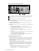
6. Enter XD to apply your changes. Enter R to restart the MP.
7. Enter CM to return to the Command menu.
8. Enter SO to set the MP user name and password. The user name must have
a minimum of 6 characters, and the password must have a minimum of 8
characters. You must set the same user name and password on every node. The
user name and password are required to access the power management device
and console, for example, when you issue the console
nodename command.
9. Enter PC (power cycle) to turn on power to the node; then choose the Boot
Option Maintenance Menu.
10. Press Ctrl/b to return to the Main menu.
11. Enter CO to connect to the console.
12. From the Boot Menu screen, which is displayed during the power on of the
node, choose the Boot Configuration Menu. Perform this step on all nodes
except the head node.
a. Choose Add a Boot Entry.
b. Choose Load File [Core LAN Gb A] as the network boot choice, which
is the Gigabit Ethernet (GigE) port.
c. Enter the string Netboot as the boot option description. This entry is
required and must be set to the string Netboot.
d. Enter N for No Boot Option when prompted for the Boot Option Data
Type.
e. Enter Y to save the entry to NVRAM.
f. Choose Exit to quit.
For more information about how to work with these menus, see the
documentation that came with your model of HP Integrity server.
13. From the Boot Configuration screen, choose the option to Edit OS Boot
Order. Perform this step on all nodes except the head node:
a. Use the navigation instructions on the screen to move the Netboot entry
you just defined to the top of the boot order.
b. Enter Y to save the entry to NVRAM.
c. Choose Exit to close the menu.
Hardware Preparation Notes 3-3