
HP XC System Software Installation Guide Version 2.1

Make your entries above the following line in the file because any entries that follow this
line will be deleted if you reconfigure yo ur system:
#XC-CLUSTER Do Not Edit Below this Line
7. Save your changes and exit the file.
8. Repeat this entire procedure for each monitoring line card, modifying the switch name and
switch address using the data in Table G-2 as a reference.
9. After you complete this procedure, you can start a Web browser and connect to the line
card using the IP address or assigned host nam e:
• http://172.20.66.1
• http://MR0N00
G.3 Configuring the InfiniBand Switch Controller C ard
The InfiniBand switch controller card provides access to InfiniBand switch control functions
through an Ethernet connection . The controller card runs a process that collects configuration
and status information from t he switch.
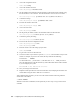
Table G-3 provides the switch names and associated IP addresses you need during the
configuration procedure. Other switch naming convention s can be used dependin g on switch
topology.
TableG-3:InfiniBandSwitchControlle
r Card Naming Conventions and IP
Addresses
Switch Order Switch Name
IP A ddress
First switch
IR0N00 172.20.66.1
Second switch
IR0N01 172.20.66.2
Third switch
IR0N02 172.20.66.3
Last switch
IR0N0n 172.20.66.n
Follow this procedure to configure network access to the InfiniBand switch controller card:
1. Ensure that an Ethernet cable from the monitoring line card’s prima ry Ethernet port
is co nnected to the appropriate E thernet port on the root administrat ion switch. This
connection is described in the HP XC System Software Hardware Preparation Guide.
2. Connect to the switch controller by pluggi ng in a s eri a l cable into the serial port on the
switch and using a terminal emulation program such as HyperTerminal. You must use
terminal settings of a baud rate of 38400, 8 d ata bits, no parity, 1 stop bit and no flow
control.
3. Press the Enter key to access the character cell i nterface to the switch.
4. Logintotheswitchwiththedefault user name and password:
login# admin
Password# 123456
5. Access the enable mode with the default password (voltaire):
ISR-9024# enable
Password# voltaire
6. Change the default admin password:
ISR-9024# password update admin
7. Change the default enable password:
ISR-9024# password update enable
Configuring Interconnect Switch Line Monitoring Cards G-5