
HP XC System Software Hardware Preparation Guide Version 2.1

Perform the following hardware preparation tasks on each HP Integrity server (models rx1620,
rx2600, and rx2620) in your CP6000 system:
1. For each node in the XC system, ensure that the power cord is connected but that the
CPU is not turned on.
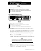
2. Follow this procedure t o connect a personal computer (PC) to the Management Processor:
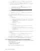
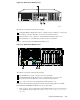
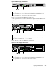
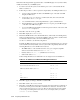
a. Conn ect a three-way DB9–25 cable to the MP D B-25 port on the back of the HP
Integrity rx2600 server.
b. Connect the CONSOLE conn ector to a null modem cable, and conn ect the null
modem cable to the PC COM1 port.
c. Use a terminal emulator, such as HyperTerminal, to open a termin al win dow.
d. Press the Enter key to access the MP. If there is no response, press the MP reset pin
on the back of the MP and try again.
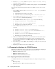
e. Log in t o the MP using the default user name and password shown on the screen. The
MP Main Menu is displayed.
3. Enter SL to clear the error logs (CLR).
4. Enter CM to display the Command Menu.
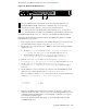
5. Ensure that all MP interfaces have had their IP address, subnet mask, and default gateway
address preconfigured before you begin the installation. This procedure is described in the
documentation t hat came with yo ur model of HP Integrity server.
Use the LC command to set the LAN configuration.
Typically, the MP on the head node is not connected to the internal network; it is connected
to the external network. By default, a 16-node system with a single utility cabinet has the
following IP addresses set for the M P on the head node:
• The MP IP address on th e extern al network i s set by you. Using the sample IP
addresses used in this manual, it is set to 192.168.0.1.
• Gateway address 172.21.0.16 (defaultbasedon16nodes).
• Subnet mask address 255.0.0.0.
In this example, IP addresses for additional nodes are assigned as shown in Table 3-2.
Table 3-2: IP Addresses for MP Power Management Devices
Node IP A ddress
First node after the head node is n15
172.21.0.15
Second node after the head node is n14
172.21.0.14
Third node after the head node is n13
172.21.0.13
.
.
.
.
.
.
n3 172.21.0.3
n2 172.21.0.2
Last node is n1
172.21.0.1
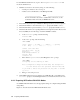
6. Enter X
D to apply your changes. Enter R to restart the MP.
7. Enter CM to return to the Command m enu.
8. Enter SO to set the MP user name and password. The user name must have a minimum of
6 characters, and the password m ust have a minimum of 8 characters. Yo u must set the
same user name and p assword on every node. The user name and password are required
to access the pow er management device and console, for exam ple, when you issue the
console nodename command.
3-14 Preparing Individual Nodes