
HP XC System Software Hardware Preparation Guide Version 2.1
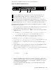
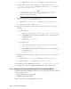
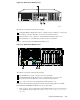
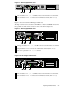
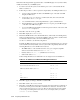

Figure 3-5: HP ProLiant DL145 G2 Server
HPTC-0144
LO100i
321
The callouts on Figure 3-1 enumerate the following:
1 The port l abeled 1 (NIC1)isusedastheconnectiontotheAdministrationSwitch(branch
or root).
2 If a Gigabit Ethernet (GigE) interconnect is configured, this p ort , labeled 2 (NIC2), is
used for the interconnect connection. Otherwise, it is used for an external connection.
3 The port labeled LO100i is used as the connection to the Console Switch.
Perform the following hardware preparation tasks for each HP ProLiant DL145 G2 node in your
XC system . Change only the values that are described in this procedure; do not change any
factory-set values unless instructed. Follow all steps in the s equen ce shown:
1. Turn on power to the node. Watch the screen carefu lly during the power-on, self-test,
and press the F10 key when prompted to access the BIOS Setup Utility.The
Lights-Out 100i (LO-100i) console management dev ice, is configured through the BIOS
Setup Utility.
The BIOS Setup Utility displays the follow ing in formation about the node:
BIOS ROM ID:
BIOS Version:
BIOS Build Date:
Write down this info rmation for future reference.
2. From the main window of the BIOS Setup Utility, scroll down and choose Boot
Options, and change the Numlock sett ing f rom Auto to Off. This allo ws the tab key
to correctly move between fields.
3. From th e menus shown across the top of the Main window, choose Advanced ->
Advanced Processor Options, and disable h yperth reading.
4. From th e menus shown across the top of the Main window, choose Advanced ->
IPMI , to display the IPMI Specification Version and the BMC Firmware Version.
5. Choose LAN Settings and do the following:
a. If the nod
e is a head node:
i. Change the IP Address Assignment from DHCP to Static.
ii. Enter the local IP address of the head node.
iii. Enter the netmask for your site.
iv. Enter the gateway address for your site.
b. If the node is a compute node, keep the default IP Address Assignment
value set to DHCP (do not change it).
c. For both the head node and com pu te nodes:
i. Change the BMC Telnet Service value from Disabled to Enabled.
ii. Change the BMC Ping Response value from Disabled to Enabled.
Preparing Individual Nodes 3-9