
HP XC System Software Hardware Preparation Guide Version 2.1
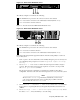
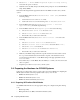
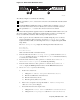
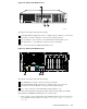
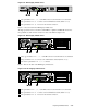
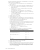

Figure 3-2: HP ProLiant DL360 G4 Server
1
The callouts on Figure 3-2 enumerate the following:
1 The iLO Ethernet is port used as the connection to the Console Switch.
2 NIC1 is used as the connection to the Administration Switch (branch or root).
3 NIC2 is used as the external connectio n.
Figure 3-3 shows the back of the HP ProLian t DL380 G4 server.
Figure 3-3: HP ProLiant DL380 G4 Server
3
2
SCSI Port 1
iLO
21
UID
PC I-X
3
100
MH z
2
100
MH z
1
133
MH z
PC I-E
2
x4
1
x4
N/A
The callouts on Figure 3-3 enumerate the following:
1 The iLO Ethernet port is used as the connection to the Co nsole Switch.
2 NIC2 is used as an external connection
3 NIC1 is used as the connection to the Administration Switch (branch or root).
Perform the following hardware preparation tasks from the iLO Setup Utility for each node
in your XC system:
1. Turn on power to the node. Watch the screen carefully dur ing the power-on self-test, and
press the F8 key when prompted to access the Integrated Lights Out Setup
Utility.
2. Choose User —> Add to create a common iLO user and password that is unique to
your site. This user name and password are required to access the console port with
the telnet cp-nodename command.
The password must have a minimum of 8 characters by default, but this value is
configurable. You must set the same user name and password on every node in the system.
_______________________ Note _______________________
The user Administrator is predefined by default, but you must create
your own user nam e and password. For security p urp oses, HP recommends
that you delete the Administrator user.
3. Choose Network –> DNS/DHCP –> DHCP Enable and set it to On to ensure that
the iLO device is requesting IP addresses through the Dynamic Host Control Protocol
(DHCP).
4. Choose Settings –> CLI –> Serial CLI Speed (bits/second) and set
the value to 115200.PresstheF10 keytosavethesetting.
Preparing Individual Nodes 3-5