
HP XC System Software Hardware Preparation Guide Version 2.1
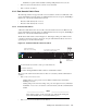
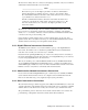

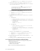

Figure 2-9: ProCurve 2650 Branch Console Switch
Po rt
LED
Vi ew
Self
Test
Clea r
Reset
Fan
Statu s
4
5
48
47
46
4543
4442
41
40
39
38
37
36
35
34
33
32
31
30
29
28
27
26
25
24
23
22
21
20
19
18
17
16
15
14
13
12
11
10
9
8
7
6
Spd m ode : of f = 1 0 Mbp s, fl ash = 10 0 Mbps , o n = 1 00 0 Mbps
10/100 Ba se-TX Ports (1 - 48)
Gi g-T
Por ts
Mi ni-
GB IC
Po rt s
1 15 17
16
18
31
32
33
34
47
48
50
49
T
M
T
M
Pow er
Fault
hp pr ocurve
swi tch
26 5 0
J48 99 A
Use onl y one (T o r M) fo r ea ch Gig abit po rt
!
1
2
3
Sp d
Lnk
Ac t
FDx
10/100Base-TX RJ-45 Ports
Connections to Node Console Ports
Gigabit
Ethernet Ports
1 Port 50 is the Gigabit Ethernet link to the Root Con s ole Switch.
The ports on this swit ch must be allocated as follows for maximum performance:
• Ports 1–10, 13–22, 25–34, 37– 44 are used f or the c onsole ports of individual no des (up
to 38 n odes).
• Ports 11, 12, 23, 24, 3 5, 36, 45–49 are unused
2.4 Interconnect Connections
The high-speed interconnect connects every node in the XC system. Each node can hav e an
interconnect card installed in the highest speed PCI-X slot (133 Mhz). Check the h ardw are
documentation to determine which slot this is. The interconnect switch console port (or
monitoring line card) also connects to the Ro ot A dministration Switch either directly or
indirectly, as described in Section 2.3.1.
You must determine the absolute maximu m num ber of nodes that could possibly be used
with the interconnect hardware that you h ave. This maximum n um ber of ports on the
interconnect switch or switches (max-node) affects the naming of the nodes in the sy stem.
The documentation that came with your interconnect hardware can help you find this number.
_________________________ Note _________________________
You may choose a number smaller than the abso lute maximum number of
interconnect ports for max-node, but you can not expand the system to a size
larger than this number in the future without comple tely re di scovering the system,
thereby renumbering all nodes in the system.
Specific considerations for connections to the Quadrics interconnect are discussed in
Section 2.4.1 and other interconnects are discussed in Section 2.4.4.
The method for wiring the System Admin istra tio n network and interconnect networks allows
expansion of the system w ithin the system’s initial interconnect fabric without recabling of any
existing nodes. If additional switch chassis or ports are added to the system as pa rt of the
expansion, some recabling may be necessary.
2.4.1 Quadrics Interconnect Connections
When the Quadrics interconnect is used, it is important that the nodes be co nnected to th e
Quadrics sw itch ports in a specific order. The order is affected by the order of the System
Administration network and Console network.
Because the Q uadrics port numbers start numbering at 0, the highest port number on the
Quadrics switch is port max-node m inus 1, where max-node is the max imum number of
nodes possible in the system. This is the port on the Q uadrics switch to which the head node
must be connected.
2-8 Making Node and Switch Connections