
HP XC System Software Hardware Preparation Guide Version 2.1


2
Making Node and Switch Connections
This chapter provid e s info rm ation about the connections betw een n odes and switches that are
required for an XC system . The topics discussed are:
• Cabinets (Section 2.1)
• Trunking and s witch choices (Section 2.2)
• Switch port connections (Section 2.3)
• Interconnect connections (Section 2.4)
2.1 Cabinets
Two types of cabinets contain the XC system hardware:
• Utility cabinet
• Application cabinet
Cabinets are used as a packaging medium. The application cabinets are optimized to meet
power, heat and density requirem ents. The ut ili ty cabinet is intended to fill a more flexible need.
Because any node can be network capable, the only distinction of nodes in the utility cabinet is
more disk I/O capability. The only strict rule is that the head node must be located in the utility
cabinet and must be connected to the Root Administration Switch (see Section 2.3.1).
In all configurations, at a minimum, the u til ity cabinet contains the head node. Nodes with
external storag e should also be contai ned in the utility cab inet .
All nodes in the utility cabinet are connected to the root switches (administration and console).
All nodes in an application cabinet are connected to the local branch switch.
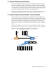
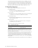
Figure 2-1: Applicatio n and Utility Cabin et s
Utility Cabinet
Application
Cabinet
Application
Cabinet
Application
Cabinet
Application
Cabinet
Root Administration Switch
2.2 Trunking and Switch Choices
For physically sm all platforms (such as a 1U H P ProLiant DL145 server), a large number of
servers (more than 30) can be placed in a single cabinet, and are all attached to a single branch
Making Node and Switch Connections 2-1