HP XC System Software Hardware Preparation Guide Part Number: AA-RWJZC-TE June 2005 Product Version: HP XC System Software Version 2.1 This manual describes how to prepare your HP Cluster Platform before installing and configuring HP XC System Software Version 2.1.
© Copyright 2003–2005 Hewlett-Packard Development Company, L.P. AMD and AMD Opteron are trademarks or registered trademarks of Advanced Micro Devices, Inc. FLEXlm is a trademark of Macrovision Corporation. InfiniBand is a registered trademark and service mark of the InfiniBand Trade Association. Intel, the Intel logo, Itanium, Xeon, and Pentium are trademarks or registered trademarks of Intel Corporation in the United States and other countries. Linux is a U.S. registered trademark of Linus Torvalds.
Contents About This Document 1 Hardware and Network Overview 1.1 1.2 1.3 1.4 1.5 2 Making Node and Switch Connections 2.1 2.2 2.3 2.3.1 2.3.2 2.3.2.1 2.3.2.2 2.3.3 2.3.4 2.4 2.4.1 2.4.2 2.4.3 2.4.4 3 1-1 1-1 1-2 1-3 1-3 Supported Cluster Platforms . . . . . . . . . . . . . . . . . . . . . . . . . . . . . . . . . . . . . . . . . . . . . . . . . . . . . . . . . Interconnect Network . . . . . . . . . . . . . . . . . . . . . . . . . . . . . . . . . . . . . . . . . . . . . . . . . . . . . . . . . . . . . .
2-2 2-3 2-4 2-5 2-6 2-7 2-8 2-9 3-1 3-2 3-3 3-4 3-5 3-6 3-7 3-8 3-9 3-10 Network Nodes and Switches . . . . . . . . . . . . . . . . . . . . . . . . . . . . . . . . . . . . . . . . . . . . . . . . . . . . . . . . ProCurve 2848 Root Administration Switch . . . . . . . . . . . . . . . . . . . . . . . . . . . . . . . . . . . . . . . ProCurve 2824 Root Administration Switch . . . . . . . . . . . . . . . . . . . . . . . . . . . . . . . . . . . . . . . ProCurve 2650 Root Console Switch . . . . . . . . . . . . . .
About This Document This document describes how to prepare the nodes in your HP cluster platform before installing HP XC System Software. An HP XC system is integrated with several open source software components. Some open source software components are being used for underlying technology, and their deployment is transparent. Some open source software components require HP XC-specific user-level documentation, and that kind of information is included in this document, if required.
HP XC Information The HP XC System Software Documentation Set includes the following core documents. All XC documents, except the HP XC System Software Release Notes, are shipped on the XC documentation CD. All XC documents, including the HP XC System Software Release Notes, are available on line at the following URL: http://www.hp.com/techservers/clusters/xc_clusters.
HP Mathematical Library The HP math libraries (MLIB) support application developers who are looking for ways to speed up development of new applications and shorten the execution time of long-running technical applications. The home page is located at the following URL: http://www.hp.
Home page for Supermon, a high-speed cluster monitoring system that emphasizes low perturbation, high sampling rates, and an extensible data protocol and programming interface. Supermon works in conjunction with Nagios to provide XC system monitoring. • http://www.llnl.gov/linux/pdsh/ Home page for the parallel distributed shell (pdsh), which executes commands across XC client nodes in parallel. • http://www.balabit.
Related Linux Web Sites • http://www.redhat.com Home page for Red Hat®, distributors of Red Hat Enterprise Linux Advanced Server, a Linux distribution with which the HP XC operating environment is compatible. • http://www.linux.org/docs/index.html Home page for the Linux Documentation Project (LDP). This Web site contains guides covering various aspects of working with Linux, from creating your own Linux system from scratch to bash script writing.
• High Performance MySQL, by Jeremy Zawodny and Derek J. Balling (O’Reilly) • Perl Cookbook, Second Edition, by Tom Christiansen and Nathan Torkington • Perl in A Nutshell: A Desktop Quick Reference , by Ellen Siever, et al. Typographical Conventions Italic font Italic (slanted) font indicates the name of a variable that you can replace in a command example or information in a display that represents several possible values. Document titles are shown in Italic font.
Ctrl/x In interactive command examples, this symbol indicates that you hold down the first named key while pressing the key or button that follows the slash ( / ). When it occurs in the body of text, the action of pressing two or more keys is shown without the box. For example: Press Ctrl/x to exit the application. Enter The name of a keyboard key. Enter and Return both refer to the same key. Note A note calls attention to information that is important to understand before continuing.
1 Hardware and Network Overview This chapter discusses the setup of hardware and networks of the XC system. The topics discussed are: • Supported HP cluster platforms (Section 1.1) • Interconnect networks (Section 1.2) • Supported console management devices (Section 1.3) • System Administration network (Section 1.4) • Console Branch of the System Administration network (Section 1.5) 1.
Table 1-2: Supported System Interconnects Gigabit Ethernet InfiniBand® Myrinet® CP3000 X X (PCIX and PCI Express) X CP4000 X X (PCIX) X CP6000 X X QsNetII® X X The Myrinet adapters can be either the single-port M3F-PCIXD-2 (Rev. D) or the dual port M3F2–PCIXE-2 (Rev. E). All adapters must be of one type only; a mix of both types of adapters is not supported. The QsNetII high-speed interconnect from Quadrics, Ltd. is the only version of Quadrics interconnects that is supported.
1.4 System Administration Network The System Administration network is a private network within the XC system that is used primarily for administrative operations. This network is treated as a flat network during run time. However, during the installation and configuration of the XC system, the administrative tools probe and discover the topology of the System Administration network. This information is used by the tools to make recommendations as to the possible configuration choices.
2 Making Node and Switch Connections This chapter provides information about the connections between nodes and switches that are required for an XC system. The topics discussed are: • Cabinets (Section 2.1) • Trunking and switch choices (Section 2.2) • Switch port connections (Section 2.3) • Interconnect connections (Section 2.4) 2.1 Cabinets Two types of cabinets contain the XC system hardware: • Utility cabinet • Application cabinet Cabinets are used as a packaging medium.
switch. The branch switch is a ProCurve Switch 2848, and two-port trunking is used for the connection between the Branch Administration Switch and the Root Administration Switch. For physically larger platforms (2U and larger) such the HP Integrity rx2600 and HP ProLiant DL585 servers, a smaller number of servers can be placed in a single cabinet. In this case, the branch switch is a ProCurve Switch 2824, which is sufficient to support up to 19 nodes. 2.
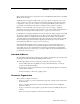
Figure 2-2: Network Nodes and Switches Specialized Role Nodes Head Node Administration Switches Console Switches Root Administration Root Console Branch Switches Branch Switches Compute Nodes 2.3.1 Root Administration Switch The Root Administration Switch for the Administration Network of an XC system can be either a ProCurve 2848 switch or a ProCurve 2824 switch for small configurations.
- Starting with port 1, the ports are used for links from Branch Administration Switches, which includes the use of trunking. Two-port trunking can be used for each Branch Administration Switch. ______________________ Note ______________________ Trunking is restricted to within the same group of 10 (you cannot trunk with ports 10 and 13). HP recommends that all trunking use consecutive ports within the same group (1–10, 13–22, 25–34, or 37–42).
- Interlink to a separate switch (10/100) containing multiple interconnect consoles • Port 24 is used as the interconnect to the Root Console Switch • Ports 11 and 12 are unused. 2.3.2 Root Console Switch Ports The following switches are supported as Root Console Switches for the Console Branch of the System Administration network. The Console Branch functions at a lower speed (10/100 Mbps) than the rest of the System Administration network. • ProCurve 2650 switch (Section 2.3.2.
2.3.2.2 ProCurve 2626 Switch A ProCurve 2626 switch can be used as a Root Console Switch for the Console Branch of the System Administration network. The ProCurve 2626 switch is shown in Figure 2-6. In the figure, white ports should not have connections, black ports can have connections, and ports with numbered callouts are used for specific purposes, described after the figure.
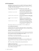
Figure 2-7: ProCurve 2848 Branch Administration Switch 2 Connections to Node Administration Ports hp procurve switch 2848 1 2 3 4 6 5 7 8 9 10 12 11 14 13 15 16 1 17 15 18 19 20 21 22 23 24 25 26 27 28 29 30 31 32 17 33 31 34 36 35 37 38 39 40 41 42 44 43 33 J4904A RPS Pow er Fault Fan LED Mode Lnk T 45 Ac t Test FDx Spd Reset Clea r Spd m ode : of f = 1 0 Mbps fla sh = 10 0 Mbps 16 on = 10 0 0 Mbps 32 18 M T 46 34 M T 47 M T 48 M
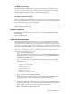
Figure 2-9: ProCurve 2650 Branch Console Switch Connections to Node Console Ports hp pr oc ur ve swi tch 26 5 0 1 2 3 4 5 6 7 8 9 10 1 11 12 13 14 15 16 17 15 18 19 20 21 22 23 24 25 26 17 27 28 29 30 31 32 33 31 34 35 36 37 38 39 40 41 42 43 44 45 46 47 48 47 33 Gi g -T Por ts J4 8 9 9 A Self Test Pow er Fault Fan Statu s Reset Por t LED Vi ew Lnk T 49 Ac t T 50 M FDx Spd Clea r Mi niGB IC Por ts Spd m ode : of f = 1 0 Mbp s, fla sh = 10
The head node is always the node connected to the highest port number of any node on the Root Administration Switch and the Root Console Switch. _________________________ Note _________________________ The head node port is not the highest port number on the Root Administration Switch. Other higher port numbers are used to connect to other switches. If the Root Administration Switch is a ProCurve 2848 switch, the head node is connected to port number 42, as discussed in Section 2.3.1.
3 Preparing Individual Nodes This chapter contains information about preparing the nodes in your HP Cluster Platform to prepare for the XC software installation. The following topics are discussed: • Firmware requirements and dependencies (Section 3.1) • General hardware preparation tasks for all cluster platforms (Section 3.2) • Preparing the hardware for CP3000 systems (Section 3.3) • Preparing the hardware for CP4000 systems (Section 3.4) • Preparing the hardware for CP6000 systems (Section 3.
Table 3-1: Firmware Dependencies (cont.) Hardware Device Dependencies QsNetII interconnect Firmware revision InfiniBand interconnect Firmware revision 3.2 General Hardware Preparations Make the following hardware preparations on all cluster platform types if you have not already done so: 1. The connection of nodes to ProCurve switch ports is important for the automatic discovery process. Ensure that all nodes are connected as described in Chapter 2. 2.
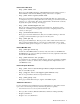
Figure 3-1: HP ProLiant DL140 G2 Server LO100i 1 2 3 HPTC-0144 The callouts on Figure 3-1 enumerate the following: 1 The port labeled 1 (NIC1) is used as the connection to the Administration Switch (branch or root). 2 If a Gigabit Ethernet (GigE) interconnect is configured, this port, labeled 2 (NIC2), is used for the interconnect connection. Otherwise, it is used for an external connection. 3 The port labeled LO100i is used as the connection to the Console Switch.
iii. 6. Change the BMC HTTP Service value from Disabled to Enabled. From the menus shown across the top of the Main window, choose Advanced -> I/O Device Configuration, and change the value of Serial Port from SIO COMM PORT to BMC COMM PORT. _______________________ Note _______________________ As described in this step, you must change the value of Serial Port before proceeding to the next step. 7. 8.
Figure 3-2: HP ProLiant DL360 G4 Server 1 The callouts on Figure 3-2 enumerate the following: 1 The iLO Ethernet is port used as the connection to the Console Switch. 2 NIC1 is used as the connection to the Administration Switch (branch or root). 3 NIC2 is used as the external connection. Figure 3-3 shows the back of the HP ProLiant DL380 G4 server.
5. Choose File –> Exit to exit the Integrated Lights Out Setup Utility and resume the power-on self-test. 6. Watch the screen carefully, and press the F9 key when prompted to access the ROM-Based Setup Utility (RBSU). Perform the following hardware preparation tasks from the RBSU for each node in your XC system: 1. From the RBSU main menu, choose Standard Boot Order (IPL), and make the following settings: a. Set the head node to boot from CD-ROM first. b.
The back side of the HP ProLiant DL145 server is shown in Figure 3-4. Figure 3-4: HP ProLiant DL145 Server PCI-X 133 Power " ! # 1 The console Ethernet port is the connection to the Console Switch (branch or root). 2 If a Gigabit Ethernet (GigE) interconnect is configured, this port is used for the interconnect connection. Otherwise, it is used for an external connection. 3 NIC1 is the connection to the Administration Switch (branch or root).
For each HP ProLiant DL145 node, log in to the Management Processor CLI and invoke the Terminal mode: 1. Establish a connection to the server by using one of the following: • A serial port connection to the console port • A telnet session to the IP address of the Management NIC _____________________ Note _____________________ For more information about how to establish these connections, see the documentation that came with your HP ProLiant server. 2. Press the Esc key and then press Shift/9.
Figure 3-5: HP ProLiant DL145 G2 Server LO100i 1 2 3 HPTC-0144 The callouts on Figure 3-1 enumerate the following: 1 The port labeled 1 (NIC1) is used as the connection to the Administration Switch (branch or root). 2 If a Gigabit Ethernet (GigE) interconnect is configured, this port, labeled 2 (NIC2), is used for the interconnect connection. Otherwise, it is used for an external connection. 3 The port labeled LO100i is used as the connection to the Console Switch.
iii. 6. Change the BMC HTTP Service value from Disabled to Enabled. From the menus shown across the top of the Main window, choose Advanced -> I/O Device Configuration, and change the value of Serial Port from SIO COMM PORT to BMC COMM PORT. _______________________ Note _______________________ As described in this step, you must change the value of Serial Port before proceeding to the next step. 7. 8.
Figure 3-6: HP ProLiant DL385 Server 3 1 100 MH z 2 1 0 0 MH z 3 1 3 3 MH z 2 1 HPTC-0145 The callouts on the figure enumerate the following: 1 If a Gigabit Ethernet (GigE) interconnect is configured, this port, labeled 2, is used for the interconnect connection. Otherwise, it is used for an external connection. 2 The port labeled 1 is the connection to the Administration Switch (branch or root). 3 The port labeled iLO is the Ethernet connection to the Console Switch.
2. Choose User -> Add to create a common iLO user and password that is unique to your site. This user name and password are required to access the console port using the telnet cp-nodename command. The password must have a minimum of 8 characters by default, but this value is configurable. You must set the same user name and password on every node in the system. _______________________ Note _______________________ The user Administrator is predefined by default, but do not use this user name.
Figure 3-8: HP Integrity rx1620 Server LAN 10/100 GSP RESETS SOFT SCSI LVD/SE CONSOLE / REMOTE / UPS PCI-X 133 HARD PCI-X 133 LAN Gb A "! USB SERIAL LAN Gb B # 1 The port labeled LAN 10/100 is the MP connection to the ProCurve Console Switch. 2 The port labeled LAN Gb A connects to the Administrative Switch (branch or root). 3 The port labeled LAN Gb B is used for an external connection. Figure 3-9 shows the back of the HP Integrity rx2600 server.
Perform the following hardware preparation tasks on each HP Integrity server (models rx1620, rx2600, and rx2620) in your CP6000 system: 1. For each node in the XC system, ensure that the power cord is connected but that the CPU is not turned on. 2. Follow this procedure to connect a personal computer (PC) to the Management Processor: a. Connect a three-way DB9–25 cable to the MP DB-25 port on the back of the HP Integrity rx2600 server. b.
9. Enter PC (power cycle) to turn on power to the node; then choose the Boot Option Maintenance Menu. 10. Press Ctrl/b to return to the Main menu. 11. Enter CO to connect to the console. 12. From the EFI Boot Manager screen, which is displayed during the power on of the node, choose the Boot Option Maintenance Menu. Perform this step on all nodes except the head node. a. Choose Add a Boot Option. b.
c. d. Choose the Select Active Standard Error Devices option from the Boot Option Maintenance Menu to enable console messages to be displayed on the screen when you turn on the system. i. Enable the Acpi(HWP0002,700)/Pci(1|1)/Uart(9600 N81)/VenMsg(Vt100+) option. ii. Enable the Acpi(HWP0002,700)/Pci(2|0) option. iii. Save the setting to the NVRAM. iv. Choose Exit to return to the Boot Option Maintenance Menu. Choose the Cold Reset menu option to apply changes. 15.
Glossary A Administrative Network The private network within the XC system that is used for administrative operations. admin branch The half (branch) of the Administrative Network that contains all of the general-purpose admin ports to the nodes of the XC system. B base image The collection of files and directories that represents the common files and configuration data that are applied to all nodes in an XC system. branch switch A component of the Administrative Network.
extensible firmware interface See EFI external network node A node that is connected to a network external to the XC system. F fairshare An LSF job-scheduling policy that specifies how resources should be shared by competing users. A fairshare policy defines the order in which LSF attempts to place jobs that are in a queue or a host partition. FCFS First come first served.
image server A node specifically designated to hold images that will be distributed to one or more client systems. In a standard XC installation, the head node acts as the image server and golden client. Integrated Lights Out See iLO interconnect Provides high-speed connectivity between the nodes. It is used for message passing and remote memory access capabilities for parallel applications.
LSF master host The overall LSF coordinator for the system. The master load information manager (LIM) and master batch daemon (mbatchd) run on the LSF master host. Each system has one master host to do all job scheduling and dispatch. If the master host goes down, another LSF server in the system becomes the master host. LVS Linux Virtual Server. Provides a centralized login capability for system users. LVS handles incoming login requests and directs them to a node with a login role.
P parallel application An application that uses a distributed programming model and can run on multiple processors. An HP XC MPI application is a parallel application. That is, all interprocessor communication within an HP XC parallel application is performed through calls to the MPI message passing library. PXE Preboot Execution Environment. A standard client/server interface that allows networked computers that are not yet installed with an operating system to be configured and booted remotely.
symmetric multiprocessing See SMP Glossary-6
Index B H baseboard management controller hardware discovery, 3-2 supported, 1-1 hardware preparation CP3000 systems, 3-5, 3-11 CP4000, 3-6 CP6000, 3-12 general, 3-2 head node, 2-1 Ethernet interface, 3-12 high-speed interconnects, 2-8 HP Integrity rx1620, 3-12 HP Integrity rx2600, 3-12 HP Integrity rx2620, 3-12 HP ProLiant DL140 G2, 3-2 HP ProLiant DL145, 3-6 HP ProLiant DL145 G2, 3-8 HP ProLiant DL360 G4, 3-4 HP ProLiant DL380 G4, 3-4 HP ProLiant DL385, 3-10 HP ProLiant DL585, 3-10 ( See BMC ) BIOS se
line monitoring card connection, 2-3 LO100, 1-2 M MP, 1-2 accessing, 3-14 MP firmware, 3-1t Myrinet interface cards revision, 3-1t N root administration switch, 2-3 ProCurve 2848, 2-2 branch administration switch, 2-6 root administration switch, 2-3 PXE, 3-12 Q QsNetII ( See Quadrics ) Quadrics, 1-1 R network interconnect, 1-1 system administration, 1-3 system administration console branch, 1-3 node head, 2-1, 3-12 nodes maximum number of, 2-8 RBSU, 3-6, 3-10, 3-12 ROM Based Setup Utility ( See RBS