HP VMA3205 and VMA3210 Array Firmware Update Guide HP Part Number: AM456-9021A Published: May 2012 Edition: 1
© Copyright 2012 Hewlett-Packard Development Company, L. P. Legal notices The information contained herein is subject to change without notice. The only warranties for HP products and services are set forth in the express warranty statements accompanying such products and services. Nothing herein should be construed as constituting an additional warranty. HP shall not be liable for technical or editorial errors or omissions contained herein. Acknowledgements Windows® is a U.S.
Contents 1 Updating the HP VMA3205 and VMA3210 Array Firmware............................4 Introduction..............................................................................................................................4 Update process overview...........................................................................................................4 Requirements for setting up the laptop.........................................................................................
1 Updating the HP VMA3205 and VMA3210 Array Firmware WARNING! The VMA array must be taken offline and rebooted during this process. All systems and applications accessing the VMA array should be shutdown. Introduction This process document outlines the steps for updating the firmware on a VMA32xx Array using a laptop or maintenance computer.
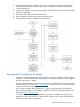
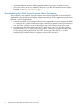
3. 4. 5. 6. 7. Connect the Laptop to the VMA32xx Array. Two communication links between the Laptop and the VMA Array will be used during the firmware upgrade; a serial link and a direct connect Ethernet link. Configure the Laptop to communicate through the serial and Ethernet links with the VMA32xx Array to be upgraded. Transfer the new VMA firmware file to the array. Run the upgrade command on the VMA array and reboot. Verify the new firmware is installed on the VMA Array.
• A standard Ethernet/network cable (length dependent on proximity of Laptop to array). • The correct version of the new VMA32xx firmware (.upg file) downloaded onto the Laptop. Example: v3000-a5-1-3-x8-slc.upg Downloading the VMA Array firmware file to the Laptop This procedure is only required once per firmware version being upgraded. Once the firmware upgrade file is downloaded to the Laptop, multiple VMA Arrays can be upgraded using the same firmware .upg file if appropriate. 1.
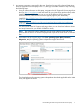
3. An internet connection is required for this step. Download a copy of the desired VMA Array firmware upgrade file to the Laptop in the C:\VMAupgrade folder created in step 2.b using the following steps: a. Using an Internet browser on the Laptop, navigate to the HP Support & Drivers page from the main http://www.hp.com web and search for your VMA Array product name, either VMA3205 or VMA3210.
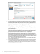
c. For each released version of firmware for the VMA32xx Arrays, there are two different connectivity modes available, either single x8 or dual x4. There is a different firmware file for each of the two connectivity modes. Select the correct firmware file that is appropriate for your Array connectivity configuration; either single PCIe cable connection (single x8) or dual PCIe cable connections (dual x4) from the Array.
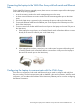
Connecting the Laptop to the VMA32xx Array with both serial and Ethernet links For the VMA32xx firmware upgrade process, there are two connections required from the Laptop to the VMA Array being upgraded: • A serial connection made to the serial management port on the array. • A direct connect Ethernet connection made to the Ethernet management port on the VMA Array. Ensure the VMA Array is powered on by connecting the power cords to the VMA Array.
1. Configure the serial connection between the Laptop and the VMA32xx Array. a. Confirm which COM port on the Laptop the serial null modem cable is connected to. If your Laptop has a single serial COM port, it will likely be COM1. b. If you are using a usb-to-serial converter cable with a serial null modem cable, the Windows Device Manager helps to identify which COM port the USB convertor is connected to after the USB cable is connected to the Laptop and the proper driver is installed.
f. g. h. Enter the correct COM port number as the serial port to be used, and click the Serial settings tab in the left Category section. The serial (PuTTY) configuration window below appears. You must set the serial settings as follows: • Baud Rate: 9600 (this might change to 115200 with future versions of array firmware) • Bits: 8 • Stop Bits: 1 • Parity: None • Carrier Detect: None (if settable) • Flow Control: Xon/Xoff To establish the serial communication with the VMA Array, click Open.
i. Login to the VMA Array with the appropriate user and password.
j. Now that you have established serial communication with the VMA Array and logged in to the CLI, determine the configured IP address of the Array Ethernet management port. Enter the following command at the prompt: show chassis controller ethernet 0 In the example above, the IP address of the VMA Array is still using the factory default IP address of 192.168.1.2. If your VMA Array has previously been configured and in use, you will likely have a different IP address established. k.
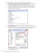
2. 14 Configure the Ethernet Connection between the Laptop and the VMA32xx Array. a. On the Laptop, launch the Control Panel utility and select Network and Sharing Center. b. On the left hand menu, select Change adapter settings. c. Select Local Area Connection. A task menu bar appears above the available connections. Select Change settings of this connection and the Local Area Connection Properties window appears. d. Select Internet Protocol version 4 (TCP/IPv4) and click Properties.
The Internet Protocol Version 4 (TCP/IPv4) Properties window displays as shown below. In the Internet Protocol Version 4 (TCP/IPv4) Properties window you will need to set an IP address that will be on the same subnet as the VMA Array so that a direct connect Ethernet communication path can be established. While the Laptop is directly connected to the VMA Array Ethernet port, you do not need to worry about possible IP address conflicts with other network interfaces.
e. To enter IP address, Subnet mask, and Default gateway values which will be compatible for a direct Ethernet link connection to the VMA Array, select Use the following IP address. If the Laptop typically uses DHCP for connection to a site network, an Alternate Configuration tab displays as shown in the above example. You can click the Alternate Configuration tab and use the alternate configuration to enter compatible IP address, Subnet mask, and Default gateway settings.
f. In this example, the VMA Array is still set with the factory default IP address of 192.168.1.2. To configure the Laptop Ethernet port with a compatible IP address in the same subnet as the VMA Array, an IP address of 192.168.1.1 is used for both the IP Address and Default gateway settings. The typical Subnet mask value of 255.255.255.0 is also configured.
h. The direct connect Ethernet link between the Laptop and the VMA Array should now be configured and able to establish communication. To verify the link is configured, launch the Command Prompt utility; and use the ping command to test the connection. NOTE: For additional Windows XP COM port Configuration information, see Additional Windows XP COM port configuration information“Windows XP COM port configuration information” (page 26).
1. Using the terminal emulator window used previously, display the current version of firmware installed on the array using the show system version command. Ensure that the new firmware being transferred is the same or newer version. WARNING! Do not attempt to backdate or downgrade to an older version of firmware on the VMA Array. The following example shows where to find the firmware version as displayed with the show system version command. 2. 3. 4.
If this is the first time that your Laptop has been used to establish a secure connection to this VMA Array, the following warning message might appear: WARNING - POTENTIAL SECURITY BREACH! The server's host key does not match the one PuTTY has cached in the registry. This means that either the server administrator has changed the host key, or you have actually connected to another computer pretending to be the server.
6. Enter the correct password for the VMA Array. The firmware file begins to transfer from the Laptop to the VMA Array. As the VMA Array firmware file is being transferred, a progress percentage count and estimated transfer time displays as shown below. Do not interrupt this firmware file transfer process. The progress status (% complete) indicates when the process is complete.
1. Return to the serial PuTTY session window. At the array CLI prompt, enter the following command: > set system sw-upgrade path local The array begins the upgrade process which takes a few minutes. The progress is reported on the screen. The firmware upgrade file is checked and validated first and then flashed across the array. When the upgrade is complete, the array prompts for a reboot in order for the changes to take effect.
2. Enter the reboot system all command. A confirmation prompt appears to ask if you intend to reboot the VMA Array. 3. Respond with y and the array reboots. You will be able to watch the process using the serial terminal console.
It is important that the array reboot process and following upgrade activity after the reboot of the VMA Array is not interrupted until the firmware upgrade process has fully completed. When the array has completed rebooting, the login prompt appears.
4. Log in as admin (default password is admin). Once up and running, you will see an alarm light on the front panel. This is standard while the individual Memory Modules are being flashed with the new firmware. The array start up screen indicates the upgraded firmware level, see above. The upgraded firmware level also shows on the front LCD display of the array. After this first reboot of the array, the array memory modules are being programmed with the new code.
> show alarm1 alarm2 alarm3 system alarms System booting (100% complete) Data plane disabled Scheduler paused > show system alarms > All alarms should be cleared and no alarms should display after the firmware upgrade process and system booting is complete. Note that the show system alarms command might display an alarm indicating the PCIe cable is not connected to the host server. This is an acceptable condition if the host server or VMA SAN gateway the array is connected to is powered off.
4. Click: Device Manager Support and other resources Contacting HP Information to collect before you contact HP NOTE: HP recommends that you record any changes that you make to your system, as well as how the changes affect system behavior.
1. 2. 3.
The following information is available on this website: • Software and firmware updates • The latest drivers and utilities • Additional documentation Phone support To contact HP customer support by phone, go to the HP Support Center (HPSC), at: http:// www.hp.com/go/hpsc. Local phone numbers are listed in your native language for help. Subscription service HP recommends that you register your product at the Subscriber's Choice for Business website: http://www.hp.com/country/us/en/contact_us.html.