
Configuring a Redundant Pair of VMA SAN Gateways - Process Guide


7
Also for the pairing of redundant gateways to be successful and supported, it is required that the
VMA SAN gateways have an identical configuration of PCIe slots, 8Gb FC HBAs and PCIe pass-thru
cards in the same I/O slots. During the pairing process you will be instructed when to install any
additionally required VMA PCIe Pass-Thru cards (P/N AM464A) and update the VMA SAN
Gateways software OE.
With Redundant VMA SAN Gateway pairs, the configuration for Ethernet ports, FC ports, array
containers and LUNs is applied the same to both gateways. For example, when limiting LUN access
to a specific set of gateway target ports, this will be applied to the same gateway target ports on both
gateways. Thus when planning for configuration of LUNs, export to initiator ports or igroups, target
port assignment and connections to FC switches, care should be made that the associated FC SAN
Switch ports are correctly zoned for desired host server discovery and access of LUNs and lunpaths.
Determine the number and sizes of LUNs which will be created on the connected VMA Arrays, which
gateway target ports will provide access to the LUNs and which host server initiator ports will be
given access to which LUNs. The LUN and access export configuration determined will initially be
configured on the ‘primary’ gateway and will later be imported to the ‘secondary’ gateway.
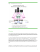
Ethernet Network Planning and Considerations
An essential component of the redundant gateway pair configuration is a reliable network. This is
achieved by:
• Bonding two Ethernet ports on each VMA SAN Gateway to increase availability of network
access to each gateway
• Configuring a virtual IP address that will be hosted by the current ‘master’ gateway for high
availability of gateway management operations and ease of use by not needing to know
which gateway is currently the acting master of the gateway pair
• Creating a tagged VLAN on the same bonded gateway Ethernet ports to allow for inter-
gateway communication
For a reliable network, it is recommended to use a minimum of two Ethernet switches with multiple
trunk links between them for higher availability. The Ethernet switches must minimally support Link
Aggregation Control Protocol (LACP) IEEE 802.1ax, Virtual LANs (VLANs) IEEE 802.1Q and must
support VLAN traffic (802.1Q) flow between switches.
A single Ethernet switch can be used, but it will then be a single point of failure for gateway and LUN
management operations. Additional intervening switches may be physically between the two Ethernet
switches and all switches will need to allow VLAN traffic to flow between the two edge Ethernet
switches being used.
For planning of the reliable network configuration, you will need to identify:
• Two IP addresses which will be assigned one to each of the two gateways being paired
• An additional IP address on the same sub-net which will be used as the Virtual IP (VIP) and
always active on the current ‘master’ gateway of the pair
• Port bonding or link aggregation mode that will be used when bonding the two Ethernet ports
on each of the two gateways. In this pairing process, ‘balance-rr’ mode is used since for
many switches explicit switch port trunking is not required. If other link aggregation modes
are used, trunking of the Ethernet switch ports connecting to the bonded gateway ports will
be required. When two Ethernet switches are being used as recommended, switches will
also need to support split trunking or distributed trunking.
• A VLAN ID which will be configured to include the same switch ports which are connected to
the VMA SAN Gateways bonded Ethernet ports. The VLAN will need to be configured on