HP VAN SDN Controller 2.2 Administrator Guide Abstract This guide is intended for network administrators and support personnel involved in: • configuring and managing HP VAN SDN (Virtual Area Network Software-Defined Networking) Controller installations • registering and activating HP VAN SDN Controller licenses The information in this guide is subject to change without notice.
© Copyright 2013, 2014 Hewlett-Packard Development Company, L.P. Confidential computer software. Valid license from HP required for possession, use or copying. Consistent with FAR 12.211 and 12.212, Commercial Computer Software, Computer Software Documentation, and Technical Data for Commercial Items are licensed to the U.S. Government under vendor's standard commercial license. The information contained herein is subject to change without notice.
Contents 1 Introduction...............................................................................................7 1.1 Supported Switches and OpenFlow Compatibility ...................................................................8 1.1.1 OpenFlow requirements.................................................................................................8 1.1.2 IPv6 Traffic..................................................................................................................
2.10.2 Displaying Event Details............................................................................................44 2.10.3 Exporting the OpenFlow Trace Log.............................................................................45 2.10.4 Filtering the OpenFlow Trace Log in a CSV file.............................................................46 2.10.5 Changing the OpenFlow Trace Interval ......................................................................48 2.10.6 OpenFlow Trace Messaging..
Hybrid mode for controlling packet-forwarding.............................................75 5.1 Overview.........................................................................................................................75 5.2 Viewing and changing the hybrid mode configuration...........................................................75 5.3 Coordinating controller hybrid mode and OpenFlow switch settings.........................................77 5.3.
9.6.1 Symptoms ..............................................................................................................103 9.6.2 Troubleshooting steps ..............................................................................................103 9.6.2.1 Packet Generator Process .................................................................................103 9.6.2.2 Run the Packet Generator Process ......................................................................
1 Introduction This document describes the configuration and management of the HP VAN Controller in standalone and team modes. The HP VAN SDN Controller is a Java-based OpenFlow controller enabling SDN solutions such as network controllers for the data center, public cloud, private cloud, and campus edge networks. This includes providing an open platform for developing experimental and special-purpose network control protocols using a built-in OpenFlow controller.
External applications can be developed in any language and are deployed on a platform outside the controller platform or on the same platform as the controller. External applications interact with the controller using the REST API services exported and advertised by the controller platform, and by native applications deployed on the controller. Because external applications are deployed outside the controller platform they cannot extend the REST API or GUI surface of the controller.
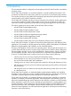
2 SDN Controller Console 2.1 Start the SDN Graphical User Interface 1. Use the Google Chrome browser to access the controller's GUI at the controller IP address: https://controller_ip_addr:8443/sdn/ui For example: https://127.0.0.1:8443/sdn/ui 2. Enter user name and password credentials, then click Login. • Default user name: sdn • Default password:skyline The main controller screen appears: Figure 1 Example of Main Controller GUI Screen with the Default Display of Alerts 2.1.
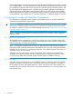
Figure 2 Click to View the SDN User Window Figure 3 The SDN User Window • Logout • Links: ◦ SDN Information Library is a link to an informational website within HP’s Software-Defined Networking business. This site offers fact sheets, case studies, white papers, product summaries, technical and business documentation, and other information to help you identify SDN solutions for your business needs.
Figure 4 Example of Resizing a Column Width 2.2 Alerts Alerts give notification of internal events that affect controller operation, and in some cases indicate that some action is needed to correct a condition. When the controller starts, it displays the Global Alerts view by default. When operating in a team, alerts generated by any team member are visible in the Alerts display for all active team members.
2.2.1 Refresh the Alert Listing The alert page is a static display. New alerts do not automatically appear in the Global Alerts view until the page is refreshed by clicking on the Refresh button. The alert notification counter runs as a background task, and as new alerts occur, the counter is incremented. Figure 6 Alert Notification Counter 2.2.
visibility, select the alert and use the Unacknowledge button to return it to an unacknowledged state. 2.2.4 Use the Alert Popup Window To Examine the Top Ten Active Alerts The alert notification counter displays the count of unacknowledged alerts. Figure 7 Unacknowledged Alerts Clicking on the symbol displays an alert popup window showing the first ten unacknowledged alerts. The listing order in the popup is the same as in the Global Alerts listing.
2.2.5 Managing the Alert Policy There is no configurable limit to the number of alerts maintained in persistent storage. Instead, the default policy is to maintain alerts in persistent storage for 14 days, and then delete them. The background task to delete alerts runs once a day by default. To change the policy, use the Configurations tab in the GUI. The configuration options for maintaining alerts include: trim.alert.age Specifies the number of days an alert remains in persistent storage.
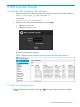
Figure 10 View the Alert Component Policy 4. Change the Alert Age-Out policy by changing the Value settings for the Key fields. Figure 11 Alert Age-Out Policy Values 5. Set the new policy by clicking on Apply in the lower right corner of the "Modify Configuration" window. 2.3 Application Manager Figure 12 Application Manager with Network Services 2.
The Application Manager supports default and add-on network services, and enables installing, upgrading, enabling (starting), disabling (stopping), and uninstalling managed applications. The default application set includes: • Path Diagnostics • Link Manager • Node Manager • Path Daemon • Topology Manager • Topology Viewer NOTE: If you stop the controller, then later restart it, all enabled (active) applications will also be restarted.
4. Click Deploy to deploy and activate the application. The new application then appears by name in the Applications list as "ACTIVE". (To use a cURL command for this procedure, see appendix cURL Commands.) NOTE: The Enable button is enabled only when an application in the DISABLED (stopped) or STAGED state is selected. 2.3.1.1.1 Stopping and Re-Starting an Application This procedure temporarily stops an active application from servicing requests, but retains the application on the system.
3. Click the Uninstall button to remove (delete) the application. The RSdoc tool does not support uninstalling an application. To use a cURL command for this task, see appendix cURL Commands. 2.3.2 Using the Application Manager in a Teamed Environment Using the Application Manager in a teamed environment is similar to the usage in a standalone controller environment. In a teamed environment, an operation performed on any of the controllers is propagated to all the other controllers in the team.
• Builds an ARP cache with MAC-IP translations of end hosts. • Maintains ARPs on a per-VID basis. • Provides the edge port details for end hosts. Example ARP table data: IP Address MAC Vid 10.250.100.1 00:af:cd:12:10:01 100 10.250.100.2 00:af:cd:12:10:20 110 10.250.100.3 00:af:cd:12:10:02 120 The Node Manager uses the services of the Topology Manager application. Path Diagnostics Determines and verifies the path taken by a specific packet from a source host to destination host.
only. This component depends on other network service components like Node Manager and Topology. Path Daemon does the following: • It registers with the controller as a "DIRECTOR". Only Directors are allowed to send a packet out. • It registers for only ARP packets and IPv4 Packets. • The flowchart below explains the Path Daemon algorithm. • Uses the Node Service to get the end hosts corresponding to the source and destination MAC addresses and the switches to which these hosts are connected.
NOTE: LinkManager operation requires LLDP to be enabled on OpenFlow switches in the network. Operation includes: • Learning and maintaining all inter-switch links in the control domain. • Providing data used by the controller topology module to construct end-to-end paths. • Deciphering port state changes. • Generates link events to notify interested listeners. • Identifies "multi-hop" links between disconnected segments of the control domain.
Figure 13 Path Daemon Flowchart 22 SDN Controller Console
2.3.4 Application requirements, required and optional attributes, and Zip file content criteria 2.3.4.1 Application requirements Any application to be installed using Application Manager on the controller must meet the following requirements: • It must be in a zip format. • The zip file must be on the same system as the controller. • It must contain an application descriptor file containing key value pairs of the attributes associated with the application, including: 2.3.4.1.
2.3.4.1.3 Application Zip File Content Criteria The application zip file contains all of the component files that make up an OSGi application. In order for the Application Manager to accept this as a valid application, certain criteria must be met: • Must contain one file with a “.descriptor” extension containing the key-value pairs described above. • Must contain at least one bundle (JAR), PAR, or WAR file. • All application component files must be valid OSGi artifacts.
Table 2 Error condition management State Description NEW > STAGEDNEW > UPGRADE-STAGED If an error condition occurs when “staging” the application, then it actually does not exist. (Error conditions in this stage clean up after themselves.) STAGED > ACTIVE If an OSGi deployment exception is encountered, the application is moved to DISABLED if it fails to deploy as it is. If a File I/O or URI exception is encountered, the application remains in the installing state.
Figure 15 Default Configurations Component Display 2.4.1 Component configuration The configuration components enable management of the controller features. The base set of controller components support the applications included in the basic controller feature set. Adding or removing an application may add or remove related configuration components included in this set, and provide more configuration control. However, direct addition or removal of configuration components is not supported.
Figure 16 Example of Configuration Component View 2.4.2 View or modify a Component Configuration 1. 2. 3. 4. 5. 6. For a given component, click on the bullet adjacent to the component name to display the Key list and configuration for that component. Click on the Modify button to view the Modify Configuration window for the selected component. For example: Click on the Value box for a key you want to modify, and enter the new value.
com.hp.sdn.adm.metric.impl.MetricManagerComponent Determines how metric data is maintained by the controller. See also Controller Metering Framework. com.hp.sdn.adm.role.impl.RoleAssertManager Provides parameters the controller uses for determining role message transmit retries and response periods. com.hp.sdn.adm.system.impl.SystemWatchdogManager Provides heart-beat status checking between SDN controllers that are running as part of a team. com.hp.sdn.api.impl.
2.5 Audit Log The Audit Log is available through both the controller GUI and the REST API, and records events related to activities, operations, and configuration changes initiated by an authorized user.
Figure 18 Example of Audit Log Showing Licensing and Teaming Activity 2.5.1 Manage the Audit Log Display In the default configuration, the log page contains up to 100 entries. Using the listing capacity options in the lower right corner of the display, you can reset the listing to a capacity of 10 or 20 entries, or to Auto, (which puts all existing log entries into a continuous listing).
Figure 19 The AuditLogManager Configuration Component Controls Audit Log Policy NOTE: In a teamed environment, the audit log shows events for all controllers in the team. As long as the trim.enabled key is set to true (the default), Audit Log maintenance is automatically managed as a background task to periodically remove audit log entries according to the trim.auditlog.age policy. Removed entries are permanently deleted from the system. 2.5.
2.7 Support Logs The Support Logs function automatically to maintain an internal record of events of interest from the operations of an active SDN controller. This information is the type of data a support engineer would request when troubleshooting an SDN installation. Figure 20 Selecting the Support Logs In a team environment, each controller maintains its own Support Logs.
4. Click on the Value field and type in the queue size you want. Figure 22 Entering the Queue Size 5. Click Apply in the lower right corner of the window. NOTE: In a controller team environment, changing the log.queue.size on any controller propagates to all active controllers in the team. 2.7.2 Log Message Levels Log message levels include the following: • ERROR • WARN • INFO • DEBUG • TRACE In the default configuration, the ERROR, WARN, and INFO levels are recorded in the Support Logs.
1. To download the support logs, click on the Export button. Figure 23 Exporting Support Logs The following dropdown box appears in the lower-left corner of the controller GUI: Figure 24 Completion of the Export Operation 2. At this point either resume interaction with the controller, or click on the dropdown arrow and take one of the indicated actions in the dropdown menu: • Open a window showing the new log zip file.
Figure 25 The Main OpenFlow Monitor Display The main display includes: • Data Path ID: The OpenFlow data path identification for each detected OpenFlow switch. These IDs also appear in the switch representations in the OpenFlow Topology display. • IP Address: The IP address associated with an OpenFlow data path instance. • Negotiated Version: The version of OpenFlow in use with the corresponding data path. 2.8.
2.8.2.1 Summary View This view includes the following related to the selected device: • Manufacturer • Hardware and software version • Serial number and device description • Device identification (Data Path ID) and IP address • TCP port on the device • Negotiated OpenFlow version (latest OpenFlow version common to both the controller and the switch) • OpenFlow table and buffer information • OpenFlow capabilities on the device Figure 27 The summary view 2.8.2.
Figure 29 Example of the Flows View for a Specific OpenFlow Device NOTE: The "Table ID" field applies to OpenFlow 1.3 and greater, but not to OpenFlow 1.0. 2.9 OpenFlow Topology The Topology viewer displays a topology of discovered switches and end nodes. The viewer creates and updates a graph of the network, and computes the broadcast tree to avoid loops and broadcast storms when hybrid mode is set to false . (See “Hybrid mode for controlling packet-forwarding” (page 75).
2.9.
2.9.1.1 Configure the topology display The Topology display includes the switches and end-nodes in the controller domain.
Figure 33 Example of end-node IP address labelling Press N again to display the end-node MAC addresses as labels in the topology diagram: Figure 34 End-node MAC addresses as labels Press N again to return to the unlabeled end-node view. Switches are always labelled with their data path ID. You can also: 40 • Add port labels to the links between switches and between switches and end nodes. • Identify flow details and options. (See Identify Flow Details and Flow Options.
In the topology display: • To display or remove port numbers for the links, click on “Ports” in the View dropdown box (or type P.) • To pin or unpin the switches and end nodes, click on “Pin All” in the View dropdown box (or type X.) • To hide or show all switch end nodes, click on “Collapse All” in the View dropdown box (or type G.
Figure 37 Finding the Shortest Path Between Two Nodes To exchange source and destination nodes, type A. To clear the source and destination flags, type Z. 2.9.1.3 Identify Flow Details and Flow Options Select Shortest Path and click on Follow Flow (or click on the switch and type I, then click on the switch again and type T). The “Switch Details” window displays the flow details and the Abstract Packet window displays selection criteria for packets moving between the Source-Destination node pair.
Using the fields in the Abstract Packet window, search for flow rules for packets having criteria dictating a path other than shortest path, for example, by entering port 80 for HTTP packets. Figure 39 Example of Searching for Flows for Specific Packet Types 2.10 OpenFlow Trace This troubleshooting tool logs OpenFlow conversations captured in messages to and from the controller and the OpenFlow devices it manages.
Figure 41 Trace Controls Starts Trace logging. In the default configuration, the trace stops after ten seconds have passed. (To change the trace interval, see “Changing the OpenFlow Trace Interval ” (page 48).) Stops Trace logging (unless already stopped due to configured timeout). NOTE: Multiple consecutive traces can be held in the Trace log. To add additional trace results after stopping a trace, just click on the button. Clears (resets) the current Trace log.
Figure 43 Displaying event details 3. Close the Event Detail window by click on the Close button. 2.10.3 Exporting the OpenFlow Trace Log If the OpenFlow Trace log displays event details, you can export this content for troubleshooting or other purposes. NOTE: Exporting an OpenFlow Trace Log places the Trace content in a CSV file that is stored in the default downloads folder specified in your web browser settings. This section shows how to export and access OpenFlow Trace Log files using Google Chrome.
1. Click on the Export button. This places the trace log contents into a CSV file in the default downloads folder in the system on which the controller is running. Check your web browser for an indication that the file has been created. See Figure 44 (page 46) for an example of this operation when running the controller on Google Chrome. Figure 44 Exporting the OpenFlow Trace Log 2. To display and filter the CSV file content, see the next section. NOTE: The browser increments the of-trace.
2. Select the DPID (Data Path ID) column. Figure 46 DPID column 3. Set the filter. Figure 47 Setting the filter 4. Apply the Filter by checking the box for data path 00.00.00.00.00.00.00.02. 2.
Figure 48 Applying the filter 5. In the resulting display, only the data filtered to data path 00:00:00:00:00:00:00:02 appears. Figure 49 Filtered Trace Log 2.10.5 Changing the OpenFlow Trace Interval The 1. 2. 3. 4. 5. 48 default trace interval is ten seconds. To set a shorter or longer interval: Click on Configurations. Open the com.hp.sdn.ctl.of.impl.TraceManager component. Click on Modify. In the Value field, enter the desired duration in seconds for active trace recording.
2.10.6 OpenFlow Trace Messaging OpenFlow Trace provides a breakdown of message events as follows: • Time • Event • DPID (Data Path ID) • Message NOTE: For information on CSV files, see RFC 4180. 2.11 OpenFlow Classes You use the OpenFlow Classes screen to view the OpenFlow classes that applications have registered with the controller. For more information about OpenFlow classes, see “About OpenFlow classes” (page 49). 2.11.
multiple SDN applications attempting to act on the same packets. In addition, many environments make it difficult to trace the origin of flow modification requests installed in switches. The HP VAN SDN Controller uses OpenFlow classes to dynamically manage the priorities of the OpenFlow rules being deployed to the network, thus enabling applications to execute their business logic without impacting on each other. 1.
2.11.4 Controller enforcement levels for OpenFlow classes The following table lists the enforcement levels that the controller can use for applications that send flows to switches. Enforcement level Description none The controller does not manage flow modification priorities or validate flow modification requests: • Applications that do not register OpenFlow classes with the controller are permitted to send flow modifications to switches.
Screen component Description Role Description Can instruct the controller to send the packet out. OBSERVER A passive observer who might examine the incoming packet and any packet-out response. Packets are given to packet listeners with role of ADVISOR first, DIRECTOR second, and OBSERVER third. Every packet listener is guaranteed to see the packet-in message. Depending on the action taken by higher altitude Directors, a lower altitude Director may be too late to influence the packet processing.
3 License Registration and Activation 3.1 Overview NOTE: SDN applications can require licenses that are separate from the licenses for the controller. Typically, you must have both a license for the controller and a license for each application. For HP SDN applications, you register the license, obtain the license key, and activate the license on the controller using the same methods you use to register and activate controller licenses.
• • High Availability “Add Controller” license (HP VAN SDN Ctrl HA E-LTU)—Enables the HP VAN SDN Controller to form a team for increased availability. The following guidelines apply: ◦ The minimum number of team members for an HP VAN SDN Controller team is three. ◦ When forming a team, only one HP VAN SDN Controller base license is required, along with at least two High Availability licenses, all on the same team leader.
NOTE: If you are registering licenses in addition to the base controller license, HP recommends you do so in the following order: 1. Register the base controller license. 2. Register any Add Nodes licenses, and then activate the last license key generated. 3. Register any High Availability licenses, and then activate the last license key generated. 4. Register any application licenses you have acquired. 3.
4. In the Email field, enter either the “Ship to” or “Sold to” e-mail address listed in your sales order confirmation, and then click Next. A license selection screen appears, as shown in Figure 53. Figure 53 Selecting licenses 5. Select the license type, enter the quantity to be registered to your Install ID, and then click Next. NOTE: • For an HP VAN SDN Ctrl Base SW w/ 50–node E-LTU license, the quantity must be 1.
Figure 54 Entering the Install ID 6. 7. 8. In the Install ID field, enter your Install ID number. (See Figure 50 (page 54). Optional: Enter a Friendly name and Customer notes for this license. Click Next. The end user software license agreement screen appears, as shown in Figure 55. Figure 55 Accepting the license agreement 9. To continue after reading the license agreement, select I accept all of the above terms, and then click Finish. The confirmation screen appears, as shown in Figure 56. 3.
Figure 56 Reviewing your registration 10. Review your license registration details, and record the License key listed. 11. Optional: To download the license key file, click Save as, and then save it to your local hard drive. 12. Optional: To e-mail the registration details: a. Enter one or more e-mail addresses, separated by a comma or semi-colon in the field provided. b. Optional: Enter Comments about this license. c. Click Send email. 13.
Figure 58 Viewing Licenses 3. To view the information for the license you just loaded, click on the Select button for that license. You will then see a screen similar to the following: Figure 59. Figure 59 Viewing your license and other information Record the license key in the above screen for use when you activate the license on the controller. 3.5 Activating a license on the controller To activate a license on the controller, add the license key.
1. Copy the license key acquired in the preceding section into the “Enter License” field in the License GUI as shown below. Adding the key to the field activates the Add button. Figure 60 Enter the License Key 2. To activate the license, click on the Add button shown in Figure 60 (page 60). The active license is now displayed in the table below the Install ID and the “Enter License” field and Add button are greyed out: Figure 61 Active License Displayed in License GUI 3.6 Managing Licenses 3.6.
3.6.1.1 Uninstalling licenses to prepare for transfer 1. Click on a license to uninstall. Figure 62 Select a License to Transfer 2. Deactivate the selected license and generate an uninstall key by clicking on the Deactivate button. Click OK when the following prompt appears: Figure 63 License Deactivation Prompt 3. Copy and record the Uninstall key appearing in the Uninstall Key field for that license. Figure 64 Example of an Uninstall Key 4.
Figure 65 Selecting licenses to transfer 4. Click the Select icon next to the license to be transferred. The license details screen appears, as shown in Figure 66. Figure 66 Reviewing details before transfer 5. Verify that this is the license you want to transfer, and then click Next. The target install ID screen appears (Figure 67).
Figure 67 Entering target install and uninstall IDs 6. In the screen in Figure 67, do the following: 1. In the Target Install ID field, enter the Install ID of the controller to which you want to transfer the license. 2. In each Uninstall field, enter a license uninstall key. (For more on acquiring uninstall keys, see Section 3.6.1.1.) NOTE: In order for the transfer process to succeed, you must enter an Uninstall value for every registered license. 3.
7. 8. 9. Review the confirmation screen details. For each license you are transferring, record the new license key so that it will be available when you add and activate the license on the new controller. Optional: To e-mail transferred license details: a. Enter one or more e-mail addresses, separated by a comma or semi-colon in the field provided. b. Optional: Enter Comments about this license transfer. c. Click Send email.
Table 4 Error messages and recommended solutions Symptom Possible cause and recommendation Redeem quantity error You specified a license quantity that exceeds what your license type supports. 1. Return to the My Network portal license selection screen. 2. Enter the correct quantity in the Redeem column for your license type: • You see an error message that your license has a maximum redeem quantity. • For an HP VAN SDN Ctrl Base SW w/ 50–node E-LTU license, the quantity must be 1.
4 SDN Controller Authentication 4.1 HP VAN SDN Controller Security Guidelines The HP VAN SDN controller communicates with different components, both internal and external to the controller, via secure channels. This section documents these channels, their defaults, and how to configure them in a deployment environment. 4.2 SDN Controller Authentication The SDN controller identifies itself via Public-Key Infrastructure (PKI) for its communication with external subsystems and other controllers.
8. If you are operating a team of controllers in your environment, turn off self-signing for inter-controller communication: Under /opt/sdn/virgo/repository/usr, change the "selfsigned" value to false for the following component: com.hp.sdn.misc.ServiceRestComponent.properties 9. If you set up a different password than the default "skyline" password for your keystore, you will need to edit /opt/sdn/virgo/configuration/tomcat-server.
4.5 Configuration Encryption Sensitive information such as tokens and passwords are stored encrypted on the SDN controller. However, to encrypt and decrypt these properties, the controller requires a master key that is passed into the controller upstart script via an environment variable. To change the default master key (recommended): 1. First, stop these services: sudo service sdnc stop sudo service sdna stop 2.
A controller restart is required if these configurations are changed. 4.7 REST Authentication The SDN controller relies on token-based authentication to authenticate its REST APIs. In other words, all REST APIs except the /auth and /rsdoc APIs require an authentication token embedded in an "X-Auth-Token" header to be included with each REST request. The /auth API allows you to obtain a token, while the /rsdoc API provides live REST API documentation information about the controller’s REST API.
} } CAUTION: Please guard this token information, as it can be used as an API key to gain access to your SDN controller REST APIs. To gain access to the REST API, include the token in the X-Auth-Token header as in the following curl example: curl -sk -H "X-Auth-Token:54a6f80a9ae243db89bfa05de4ced51d" https://:8443/sdn/v2.0/systems One can continue using the same token for different SDN controller APIs within the default 24-hour period since token creation.
4.8.2 Running the Controller Without Jar-Signing Validation The SDN controller enforces jar-signing validation by default. For an experimental/development environment where unsigned applications need to be deployed, jar-signing validation can be turned off altogether: 1. Stop the SDN controller sudo service sdnc stop 2. Modify the /opt/sdn/virgo/bin/dmk.
crlFile=""/> For the above change to take effect, restart the controller. 4.10 SDN Administrative REST API The main SDN Controller daemon (sdnc) is accompanied by an ancillary daemon process (sdna), which runs under user sdnadmin in order to grant it access to some elevated privileges. The administrative REST API can be used to securely perform various management functions in a privileged context.
To disable access to the Virgo Admin UI, either remove the following file or move it to a safe location outside the pickup directory: 4.12 Virgo Console Access This allows Virgo administrative access via ssh/telnet. This service is disabled by default. The following file configures these properties and will require the controller to restart to recognize the new settings: /opt/sdn/virgo/pickup/org.eclipse.virgo.management.console_3.6.2.RELEASE.jar 4.
Table 5 iptables Rules 74 Target prot opt source Destination ACCEPT tcp – 127.0.0.0/8 anywhere tcp dpt:2181 REJECT tcp --anywhere tcp dpt:2181 reject-with icmp-port-unreachable ACCEPT tcp – 127.0.0.0/8 anywhere tcp dpt:9160 REJECT tcp --anywhere anywhere tcp dpt:9160 reject-with icmp-port-unreachable ACCEPT tcp – 127.0.0.
5 Hybrid mode for controlling packet-forwarding 5.1 Overview The hybrid mode setting determines which packet-forwarding decisions will be made by controlled OpenFlow switches and which of these decisions will be made by the controller itself. • If hybrid mode is enabled (the default setting), the controller delegates normal packet forwarding to the controlled switches, but overrides these switches for non-standard packet-forwarding decisions required by installed applications for specific packet types.
Figure 72 Open the Controller Manager configuration Figure 73 Select the hybrid.mode Value field In Figure 73 (page 76), the hybrid.mode field shows the current setting. Continue with the following steps if you want to change the setting. 6. 76 Set hybrid.mode to one of the following: • true (the default): Enables hybrid mode. The controller makes packet-forwarding decisions required by installed applications. • false: Disables hybrid mode The controller makes all forwarding decisions. (Release 2.
7. Restart the controller. In a controller team environment, restart all controllers in the team. a. Close any instance of the web interface in which the controller may be running. b. Using the command prompt at the root access on the Ubuntu system (sudo), restart the controller with the following: ~$ sudo service sdnc restart NOTE: In a controller team environment, a configuration change on one controller propagates to the other controllers on the team.
Table 7 Controller settings to support hybrid mode Controller Configurations Component Key Comments com.hp.sdn.ctl.of.impl.ControllerManager hybrid.mode com.hp.sdn.ctl.linkdisco.impl.LinkManager learn.multihop.links Enable this setting if there are switches in the network that are not controlled by the controller, but the topology across these switches must be visible to the controller.
Figure 74 Configuration components to modify for hybrid mode support CAUTION: In ProVision OpenFlow switches, the ip-control-table-mode command option for including the IP control table in the OpenFlow packet processing pipeline is not supported in release 2.2 of the HP VAN SDN Controller. For more information, see the documentation for the ProVision OpenFlow switches. CAUTION: ProVision switch hardware-only mode (shown in the command below) is not currently supported by the VAN SDN 2.
5.4 Controller packet forwarding operation 5.4.1 Hybrid mode disabled Figure 75 Controller operation with hybrid mode disabled When hybrid mode is disabled (set to "false"), the controller examines and directs the packets in all flows for the given OpenFlow instance. The controller forwarding decisions for flows in a given instance are based on the requirements of the installed applications. The forwarding decision is communicated to controlled switches through OpenFlow.
5.4.2 Hybrid mode enabled Figure 76 Controller operation with hybrid mode enabled When hybrid mode is enabled (the default), the specific packet types for which the controller monitors and overrides switch forwarding rules depends on the applications installed and running in the controller.
6 Team Configuration Standalone controller operation provides management for the OpenFlow switches in a network. However, it does not provide high availability (HA), with the result that a controller failure leaves the network in an unmanaged state. Configuring a team of controllers and a corresponding controller region creates a high availability network with failover capability, resulting in a continuously managed network in the event that a controller in the team goes down.
4. On the selected controller, acquire an Authentication Token. Use the following cURL command, with the controller IP address, to acquire the token: curl --noproxy -X POST --fail -ksSfL --url "https://:8443/sdn/v2.
{"name":"member_2","ip":""}, {"name":"member_3","ip":""}]}}' NOTE: The member-ip-addr should be the IP address of the controller chosen to configure the team. 3. After executing the command in step 2, the team elects a team leader. The team leader then configures all team members and normal controller operation begins in the domain. 6.2.
NOTE: The IP address used in this step should be the same as used in step 1. curl --noproxy 192.0.2.119 --header X-Auth-Token: 10f728e477cb4612b07069f339d0ca29 --fail -ksS --request POST --url https://192.0.2.119:8443/sdn/v2.0/team --Data-binary '{"team":{"name":"Test_Team","ip":"192.0.2.100","systems":[{"name":"Athos", "ip":"192.0.0.119"},{"name":"Porthos","ip":"192.0.0.125"}, {"name":"Aramis","ip":"192.0.0.127"}]}}' {"team":{"name":"Test_Team","ip":"192.0.2.100", "systems":[{"name":"Athos","ip":"192.0.
2. Using the token acquired in the preceding step, execute this cURL command to display the team configuration: curl --noproxy --header "X-Auth-Token: " --fail -ksSfL --request GET --url https://:8443/sdn/v2.0/team For example: curl --noproxy 192.0.2.100 --header "X-Auth-Token: " --fail -ksSfL --request GET --url https://192.0.2.119:8443/sdn/v2.0/team The resulting team configuration output includes the following: {"team": { "name":"Test_Team", "ip":"192.0.2.
-ksSfL --request DELETE --url https://:8443/sdn/v2.0/team The resulting output includes the following: { "success": [ {"ip":"192.168.56.19"}, {"ip":"192.168.56.25"}, {"ip":"192.168.56.25"}]} 6.5 Controller Fault Tolerance The threshold for controller fault tolerance is 2n+1, where n is the number of failed controllers allowed in an active team. HP VAN SDN Controller teaming supports a team of three controllers.
Message Description Unable to form a quorum. Team configuration has failed on a majority of systems. e.g. a team of three systems has experienced failures on two systems Unprogramming team alias < ip-address > failed. See Team Alias Note. 6.6.1 Team Alias Note An IP Address (North-Bound IP) alias is created on the node that is elected as team leader to allow a controller team to be accessible with a single IP Address no matter which controller is the leader.
7 Region Configuration 7.1 Overview This chapter describes the configuration needed to support High Availability (HA) for HP VAN SDN controllers to OpenFlow switches. This is done by creating region configurations in the controllers using the REST APIs provided by the Role Orchestration Service (ROS). Putting the region configurations in place in a controller team ensures seamless failover and failback among the configured controllers for the specified network devices in a region.
7.2 Create a Region A region should have a minimum of two controllers. This example illustrates the cURL command to use for creating a new region definition with the following controllers and devices: Master Controller Slave Controllers OpenFlow Switches IP Address Name IPAddresses Names 192.146.194.80 Controller_1 192.146.194.103 Controller_2 10.250.100.20 192.146.194.38 Controller_3 10.250.100.
curl --noproxy --header "X-Auth-Token:" --header "Content-Type:application/json" --fail -ksS --request GET --url https://:8443/sdn/v2.0/regions/ For example, the following command acquires the region ID (uid) for the controller team in the region created in Create a Region. curl --noproxy 192.146.194.80 --header "X-Auth-Token:54a6f80a9ae243db89bfa05de4ced51d" --header "Content-Type:application/json" --fail -ksS --request GET --url https://192.146.194.
], \"devices\": [ { \"ip\": \"10.250.100.20\" }, { \"ip\": \"10.250.100.21\" }, { \"ip\": \"10.250.100.22\" } ] }}' 7.5 Refresh a Region In case of an inconsistency, and as a troubleshooting feature, you can initiate a re-assertion of the configured roles in a region by using the "refresh" cURL command. This command refreshes all devices in the region.
8 Backup/Restore This chapter describes controller backup and restore actions using cURL commands. For REST APIs for enabling backup and restore, go to /systems in the RSdoc facility on the controller. (Using a Google Chrome browser window on the controller, enter https://< system_ip_address>:8443/api .) You cannot use RSdoc to download or upload files. NOTE: Only one backup, restore, upload, or download operation can be active at any time on a given controller or controller team.
NOTE: The default domain name is "sdn". The default username is also "sdn". The default password is "skyline". The controller does not save a non-default domain, user name, or pass-word across a backup. Changing these settings to non-default values and later backing up the controller, resets these settings to their defaults in the backup file. Later restoring the backup to the controller resets the domain, user name, and password to their default settings in the controller.
curl --noproxy --header "X-Auth-Token:" --fail -ksSfL --request PUT "https://<:8443/sdn/v2.0/systems"controller_uid>" --data-binary '{"system":{"ip":""}}' 4. Perform the actual backup using the following cURL command: curl --noproxy --header "X-Auth-Token:" --fail -ksS --request POST --url "https://<:8443/sdn/v2.
• • A completed backup should be downloaded from the controller to another location for safekeeping. Include the IP address in the backup filename, so you can easily determine which backup belongs to which controller in a team. Recommended file naming is: ◦ sdn_controller_backup_.zip ◦ sdn_controller_backup_.zip.MD5 Store the backups and associated checksum (MD5) files you take of each controller in the team together, so they can easily be retrieved for a future restore.
2. 3. Before restoring a controller, set CTL_RESTORE_INSTALL_MODE=True in the ~/.sdn_install_options file in the home directory. If this file is not present in the directory, create it with the CTL_RESTORE_INSTALL_MODE entry. If the file is already present, ensure that it includes the CTL_RESTORE_INSTALL_MODE entry.
5. Acquire the controller uid for the controller backup: curl --noproxy --header "X-Auth-Token:" --fail -ksSfL --request GET --url https://:8443/sdn/v2.0/systems 6. Use the following cURL command to set the IP address: curl --noproxy --header "X-Auth-Token:" --fail -ksSfL --request PUT "https://:8443/sdn/v2.0/systems/" --data-binary '{"system":{"ip":""}}' 7.
9. Once the controller restore is complete, change CTL_RESTORE_INSTALL_MODE equal to False in the "~/.sdn_install_options" file on each controller so that it does not impact a future installation. This is because a future installation of the controller may not involve starting in recovery mode. (This is the opposite of step 2 of To Restore a Controller from a Backup.) You can follow the restore progress in the controller log found at /opt/sdn/backup/restore.log.
9 Troubleshooting 9.1 Host location not learned by controller In a topology where two or more controlled switches connect to the same uncontrolled switch, the controller will not learn the location of hosts connected to the uncontrolled switch. 9.2 Unexpected network or service problem Changing the hybrid.mode configuration without also restarting the controller and disabling, then re-enabling each controlled OpenFlow instance in the OpenFlow switches can result in network or service problems.
9.3 Application management exceptions Table 8 Application management exceptions • ApplicationDisableException: Indicates that an application cannot be disabled. ◦ Occurs when an app is STAGED or UPGRADE_STAGED, or something else has gone wrong (specified in error message) ◦ HTTP code: 500 • ApplicationEnableException: Indicates that an application cannot be enabled. ◦ Occurs when an app is not DISABLED, or something else has gone wrong (as specified in the error message).
9.4 Notes on measuring flows (packets) per second For measuring flows-per-second for performance testing, the learn.IP option in com.hp.sdn.ctl.nodemgr.impl.NodeManager (under Configurations/Component) in the controller GUI should be set to "false" due to the additional processing required. (The default setting is "true".) 1. In the controller web interface, select the “Configurations” option. 2. Select the com.hp.sdn.ctl.nodemgr.impl.NodeManager component. 3. Click on the Modify button.
9.5 Application management error conditions • • • If the Application Management framework is able to detect a failure to start an application in the OSGi runtime environment, the application is automatically moved to the DISABLED state. ◦ Correct the OSGi runtime conditions. ◦ Enable the application. •If an unexpected error condition occurs when manipulating an application (file I/O exception, missing files, etc) the application will be left in a transitive state.
9.6.2.2 Run the Packet Generator Process 1. Authenticate using the following cURL command: curl --noproxy -X POST --fail -ksSfL --url "https:// :8443/sdn/v2.0/auth" -H "Content-Type: application/json --data-binary '{"login":{"domain": "sdn","user": "sdn","password": "skyline"}} 2. Collect the source and destination end host details using NodeManager REST API via RsDoc/CLI Eg: https://:8443/sdn/v2.0/net/nodes Eg: https://:8443/sdn/v2.
}, { "ip": "10.0.0.8", "mac": "e6:12:8e:f9:03:64", "vid": 0, "dpid": "00:00:00:00:00:00:00:08", "port": 1 }, { "ip": "10.0.0.7", "mac": "12:94:57:f7:cb:66", "vid": 0, "dpid": "00:00:00:00:00:00:00:07", "port": 1 }, { "ip": "10.0.0.4", "mac": "82:a3:85:71:63:bf", "vid": 0, "dpid": "00:00:00:00:00:00:00:04", "port": 1 } ] } 3. Register a packet which needs to be injected in the network for tracing the path. For example TCP packet with destination port as 21. POST https://:8443/sdn/v2.
"ip_ident": 0, "ip_dscp": "CS0", "ip_ecn": "NOT_ECT" }, "tcp": { "tcp_src": 12345, "tcp_dst": 20 } } } 4. Set the observation post on the switch where the destined end host is connected. post /diag/observations. NOTE: An alert is generated for an operation such as setting or removing an observation post. These alerts can be viewed by using the Alert Log in the controller GUI. Destination end host ( 00:00:00:00:00:05 ) is connected to switch having dpid as 00:00:00:00:00:00:00:01 .
"in_phy_port":9 } ], "packet_uid": "2096432597", "status": "OK", "type": "TCP", } } 7. If the packet has reached the destined observation post , it means the connectivity is between the source and the end host is good. For example, user sees the "status": "OK", // inference packet reached the observation above. 8. 9. In case the destined observation post has not received the trace packet , it means it is being dropped by one of the intermediate hops.
10 Support and other resources To learn how to contact HP, obtain software updates, submit feedback on documentation, and locate links to HP SDN websites and other related HP products, see the following topics. 10.
10.4.1 Care Packs To supplement the technical support provided with the purchase of a license, HP offers a wide variety of Care Packs that provide full technical support at 9x5 or 24x7 availability with annual or multi-year options. To purchase a Care Pack for an HP SDN application, you must have a license for that application and a license for the controller. For a list of Care Packs available for the controller and HP SDN applications, see: http://www.hp.
11 Documentation feedback HP is committed to providing documentation that meets your needs. To help us improve the documentation, send any errors, suggestions, or comments to Documentation Feedback (docsfeedback@hp.com). Include the document title and part number, version number, or the URL when submitting your feedback.
A cURL Commands If the cURL utility is not installed on the machine where the HP VAN SDN Controller is installed, use the following command to download it: sudo apt-get install curl CAUTION: Credential information (user name, password, domain, and authentication tokens) used in cURL commands may be saved in the command history. For security reasons, HP recommends that you disable command history prior to executing commands containing credential information.
1. Use the following command to authenticate with the controller and create a security token: curl -sk -H 'Content-Type:application/json'-d '{"login":{"user":"MyUser","password":"MyPassword","domain":"sdn"}}' https://MyControllerIP:8443/sdn/v2.0/auth • Replace MyUser and MyPassword with your actual values. • Replace MyControllerIP with your controller IP address. NOTE: If you are installing a High Availability license, enter the IP address of the lead controller.
1. If your previous cURL session has closed or timed out, re–enter the authentication command to obtain a new token: curl -sk -H 'Content-Type:application/json'-d '{"login":{"user":"MyUser","password":"MyPassword","domain":"sdn"}}' https://MyControllerIP:8443/sdn/v2.0/auth • Replace MyUser and MyPassword with your actual values. • Replace MyControllerIP with your controller IP address. NOTE: If you are installing a High Availability license, enter the IP address of the lead controller.
Example 5 Installed license output { "license" : { "install_id" : 1249679, "serial_no" : 13, "license_metric" : "HA Controller", "product" : "HP VAN SDN Ctrl Base", "metric_qty" : 500, "license_type" : "PRODUCTION", "base_license" : false, "creation_date" : "2013-09-06T00:26:52.248+0000", "activated_date" : "2013-09-06T00:26:52.248+0000", "expiry_date" : "2014-01-14T00:26:52.248+0000", "license_status" : "ACTIVE" } } A.2.3 Uninstalling licenses to prepare for transfer To uninstall licenses: 1.
Example 7 All installed licenses output { "licenses" : [{ "install_id" : 12491640, "serial_no" : 12, "license_metric" : "Controller Node", "product" : "HP VAN SDN Ctrl Base", "metric_qty" : 52, "license_type" : "PRODUCTION", "base_license" : true, "creation_date" : "2013-09-06T00:26:52.248+0000", "activated_date" : "2013-09-06T00:26:52.248+0000", "expiry_date" : "2014-01-14T00:26:52.
Example 8 License uninstall key output { "license" : { "install_id" : 1249679, "serial_no" : 13, "license_metric" : "HA Controller", "product" : "HP VAN SDN Ctrl Base", "metric_qty" : 500, "license_type" : "PRODUCTION", "base_license" : false, "creation_date" : "2013-09-06T00:26:52.248+0000", "activated_date" : "2013-09-06T00:26:52.248+0000", "expiry_date" : "2014-01-14T00:26:52.
Example of listing information about an application curl --noproxy 15.255.125.107 --header “X-Auth-Token: 85f7c48b65394afc97de434b5aa8fe05” -ksSL --request GET --url https://15.255.125.107:8443/sdn/v2.0/apps/com.hp.snd.ctl.diag Example output: {"app": {"uid":"com.hp.sdn.ctl.diag", "name":"Path Diagnostics", "version":"2.1.0.SNAPSHOT", "desc":"Path Diagnostic Utility", "vendor":"Hewlett-Packard", "state":"ACTIVE", "deployed":"2014-02-25T00:23:17.839Z"}} A.3.
{"app": {"uid":"com.geewiz", "name":"GeeWiz", "version":"1.0.0", "desc":"Gee Wiz event production", "vendor":"Gee Wiz, Inc.", "state":"ACTIVE", "deployed":"2014-02-26T01:00:58:111Z"}} A.3.6 Upgrade an application curl --noproxy --header “X-Auth-Token:” -ksSL --request POST--url https://:8443/sdn/v2.0/apps//action -d upgrade Example of upgrading an application curl --noproxy 15.255.125.
curl --noproxy 15.255.125.107 --header “X-Auth-Token: 85f7c48b65394afc97de434b5aa8fe05” -ksSL --request POST --url https://15.255.125.107:8443/sdn/v2.0/apps/com.geewiz/action -d cancel A.3.10 Delete an application This curl request is used to shutdown and completely remove all application versions. It has no output. curl --noproxy --header “X-Auth-Token:” -ksSL url https://:8443/sdn/v2.
curl --noproxy --header "X-Auth-Token:" --fail -ksS -L -f --request GET --url "https:// :8443/sdn/v2.0/systems" A.4.6 Verify Backup Status curl --noproxy --header "X-Auth-Token:"https:// /sdn/v2.0/backups/ A.4.7 Download Zip and MD5 Backup Files to Another Device curl --noproxy --header "X-Auth-Token:" --fail -ksSfL --request GET --url "https://:8443/sdn/v2.
B Scripts B.1 Configuring a Controller Team This script configures a team composed of three controllers. NOTE: Because the scripts in this appendix cross page boundaries, be careful to avoid including the page number when copying a script. Copying a script one page at a time can prevent inclusion of page numbers. ========== ===== =================================================== #!/bin/bash #------------------------------------------------------------------------------# Copyright 2013 Hewlett Packard Co.
# # Backup a Team #------------------------------------------------------------------------------export BACKUP_DIR="/opt/sdn/backup" export BACKUP_TEAM_DIR="/opt/sdn/team_backup" export TEAM_BACKUP_STATUS_FILE="$BACKUP_TEAM_DIR/teamBackup_status" export TEAM_BACKUP_LOGFILE="$BACKUP_TEAM_DIR/teamBackup_log.
# Verifies the success of the backup. #-----------------------------------------------------------------------------function verifyBackupStatus { local nodeIndex=$1 local backupIP=${ipArr[$nodeIndex]} local backupSession=${backupsession[$nodeIndex]} local backupUrl="https://$backupIP:8443/sdn/v2.
exit $1 } #-----------------------------------------------------------------------------# Function get ( ) # Performs a GET.
} }" # Attempt to authenticate and extract token if successful. auth=$(curl --noproxy $nodeIP -X POST --fail -ksSfL --url "$url" \ -H "Content-Type: application/json" --data-binary "$login" 2>&1) if [ $? -ne 0 ]; then teamBackup_log "Unable to authenticate as user $user in $domain domain." exitBackup 1 fi authToken=`extractJSONString "$auth" "token" | sed '/^$/d'` if [ $restore_mode -ne 1 ] && [ "$authToken" == "" ]; then teamBackup_log "Failed to get the authentication token.
for (( k=0; k<$BACKUP_WAIT_COUNT; k++ )); do sleep 10 verifyBackupStatus $leaderIndex if [ $backup_complete -le 0 ]; then teamBackup_log "Backup on the leader node completed successfully." break fi done if [ $backup_complete -gt 0 ]; then teamBackup_log "Backup of the leader node took longer than $waitTime min. Aborting backup..." teamBackup_log "To increase backup wait time, change BACKUP_WAIT_COUNT in the script." exitBackup 1 fi # Copy all the backup files from each node in the team onto the leader node.
fi done teamBackup_log "IP $myip is not a valid member of the team, exiting." exitBackup 1 } #-----------------------------------------------------------------------------# Function upload_backup_file ( ) # Uploads backup and MD5 files to the specific nodes of the team.
fi uuidURL="https://${restoreIpArr[$i]}:8443/sdn/v2.0/contact" restoreUUID[$i]=`get ${restoreIpArr[$i]} ${restoreAuth[$i]} "$uuidURL"` if [ "${restoreUUID[$i]}" == "" ]; then teamBackup_log "Failed to get the UUID for ${restoreIpArr[$i]}, can't start restore." exitBackup 1 fi restoreUUID[$i]=`extractJSONString "${restoreUUID[$i]}" "uid" | sed '/^$/d'` teamBackup_log "UUID for ${restoreIpArr[$i]} is ${restoreUUID[$i]}" # Upload the backup files to a specific node.
errorCode=$? let "attempts = $attempts + 1" if [ 35 -eq $errorCode ]; then teamBackup_log "SSL error on POST to $postUrl, retrying..." continue; fi break; done echo $postRes } #-----------------------------------------------------------------------------# Function put ( ) # Performs a PUT of the specified data.
echo " path - where to copy the file from on the remote system" exit 1 fi create_restoreDir user="$1" echo -n "Enter Controller Password: " read -s pass echo domain="$2" file="" if [ $# -eq 3 ]; then teamBackup_log "Starting the team restore. This will restore all the nodes in a team." file=$3 else teamBackup_log "Starting selective restore on specified IPs. This restore will happen only on the specified nodes.
Glossary C cluster A set of datapaths where each has at least one direct link to another datapath in the cluster, i.e. a set of directly interconnected switches that all support OpenFlow. D datapath An OpenFlow instance. H HA High Availability O OSGi artifacts The individual building blocks of the SDN controller and the applications that can run on the controller. Includes Java jar files, plan xml files, and other files contained in an application zip file.