Implementing disaster recovery for HP Integrity Virtual Machines with Metrocluster and Continentalclusters on HP-UX 11i Technical white paper Table of contents Executive summary............................................................................................................................... 2 Introduction ......................................................................................................................................... 2 Audience ...........................................
Executive summary The purpose of this white paper is to describe the steps needed to configure an HP Integrity Virtual Machine (VM) as a package in HP Metrocluster and HP Continentalclusters environments. In the configuration that uses HP Metrocluster software, a Metrocluster is formed using VM host systems as nodes in the cluster, and the VMs are encapsulated within Metrocluster packages.
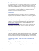
The steps required to configure a VM into a Metrocluster package are explained with a sample configuration of Metrocluster Continuous Access XP/P9000. This Metrocluster Continuous Access XP/P9000 configuration information can be easily extended to Metrocluster Continuous Access EVA and Metrocluster SRDF configurations. The specific differences are cited in detail where applicable. Assume that a 4-node Serviceguard cluster is created.
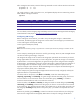
Figure 1. Metrocluster configuration for setting up virtual machines Configuring Metrocluster packages Let’s configure a Metrocluster package called vmmetropkg using this setup. To configure a virtual machine into a Metrocluster package, the VM must first be configured individually on all the cluster nodes and must have the same name on all cluster nodes. For our example, we’ll use vmmetro as the VM name. Setting up virtual machines Complete the following procedure to set up a virtual machine: 1.
After creating the VM switches, enter the following commands on each node to start the virtual switch: # hpvmnet –b # hpvmnet –b –S –S vs1 vs2 The virtual switches vs1 and vs2 are active now, and hpvmnet displays the new states along with the MAC address of the physical device: #hpvmnet Name Number State Mode PPA MAC address IP address localnet 1 Up Shared N/A N/A N/A vs1 2 Up Shared lan0 0x00306ea70bb3 16.89.140.178 vs2 3 Up Shared Lan1 0x00306e4a28a4 192.244.64.
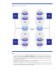
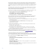
group dgVM and configuring the VxVM disk group vmdatadg on top of it are given later in this document. Similarly, in a Metrocluster SRDF environment, this disk group should be configured as an SRDF device group. In a Metrocluster Continuous Access EVA environment, this disk group should be configured as an EVA data replication (DR) group. Tables 1 and 2, respectively, describe the VxVM disk group layouts on Node1 and Node2, and on Node3 and Node4.
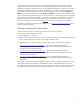
Figure 2. VM guest storage in the Metrocluster Notes: 1. If required, the VxVM disk groups vxpriosdg and vxpriexedg can be shared among all nodes in the primary site. Similarly, the VxVM disk groups vxsecosdg and vxsecexedg can be shared among all nodes in the recovery site. This way the OS image and application binaries would be shared by VMs on different nodes in the same data center.
Creating a Continuous Access XP/P9000 device group You need to create a Continuous Access XP/P9000 device group on every node in the cluster. To create a device group, complete the following steps: 1. Copy the horcm.conf file in /etc directory into an instance specific file in all nodes in DC_1and DC_2 if not already done previously. # cp /etc/horcm.conf /etc/horcm0.conf 2. Edit the HORCM_MON and HORCM_CMD sections of the horcm0.conf file. For instructions on doing this, see the /etc/horcm.conf file. 3.
2. Create the device group pair for dgVM with the paircreate command: # paircreate –g pkgA –f never –vl –c 15 to create volume pairs from Node1 [For fence level never] 3. To verify that the pair volumes are created with an appropriate fence level, run the following command: # pairdisplay –g dgVM Creating an EMC Symmetrix device group You need to create a device group on every node in the cluster. To create a device group, complete the following steps: 1.
After a DR group’s creation, only the source volume (primary volume) is visible and accessible with read/write mode. The destination volume (secondary volume), by default, is not visible, and it is inaccessible to its local hosts. The destination volume access mode needs to be changed to read-only mode before the DR group can be used. The destination volume needs to be presented to its local hosts.
2. Initialize disks to be used by VxVM by running vxdisksetup command on the primary site. # /opt/VRTS/bin/vxdisksetup –i c4t2d5 # /opt/VRTS/bin/vxdisksetup –i c4t2d6 Note: The following information provides details on how to determine the mapping between array device names and the native OS names. For Metrocluster Continuous Access XP/P9000, use raidscan command.
13. Deport the disk group. # vxdg deport vmdatadg 14. Restore the device groups to its original state.
2. On each node in the recovery site, import the following disk groups: vmsecosdg, vmsecexedg, and vmdatadg; and create the virtual machine vmmetro: # hpvmcreate –P vmmetro –a dvd:scsi::disk:/var/os/hpvm.0505_OE.Gold1.
Guest Device ====== disk disk disk dvd Adapter ======= scsi scsi scsi scsi Bus === 0 0 0 0 Dev === 0 0 0 0 Ftn === 0 0 0 0 Tgt === 0 1 2 3 [Network Interface Details] Interface Adapter Name/Num ========= ======= ======== Vswitch lan vs1 Lun === 0 0 0 0 [Misc Interface Details] Guest Physical Device Adapter Bus Dev ====== ======= === === serial com1 PortNum ======= 2 Ftn === Physical Device ========================= /dev/vx/rdsk/vmpriosdg/osvol /dev/vx/rdsk/vmpriexedg/oraclevol /dev/vx/rdsk/vmdata
where: -P vm_name indicates the virtual machine name -m specifies whether maintenance mode is enabled or disabled (1 = Enabled, 0 = Disabled) -L creates a legacy package (default is modular) -V indicates verbose -Q quietly performs command, taking default actions without additional prompts -s sanity checks the specific command, but does perform the requested action The script asks you to confirm the following actions: • Creation of a failover package • Distribution of the package to all the cluster nodes Th
Complete the following steps to create a modular package using Metrocluster Continuous Access XP/P9000: 1. Run the following command to include the Metrocluster Continuous Access XP/P9000 module in the existing Serviceguard modular package configuration file: # cmmakepkg –i /etc/cmcluster/guest-name/guest-name.config –m dts/mcxpca MC_guest-name.config Note: When using Metrocluster Continuous Access EVA and Metrocluster SRDF, include dts/mccaeva and dts/mcsrdf modules respectively. 2.
AUTO_FENCEDATA_SPLIT=1 AUTO_SVOLPSUS=0 AUTO_NONCURDATA=0 MULTIPLE_PVOL_OR_SVOL_FRAMES_FOR_PKG=0 WAITTIME=300 PKGDIR=/etc/cmcluster/vmmetro FENCE=never (or data or async as the case may be) DEVICE_GROUP=dgVM CLUSTER_TYPE=”metro” HORCTIMEOUT=360 3. Once the _xpca.env file has been modified for the specific package, copy this file to all nodes in the cluster.
Troubleshooting Metrocluster VM problems This section describes the various problems that you can face while using Integrity Virtual Machines. Each problem is followed by the associated workaround or solution. If the virtual machine does not start up when you try to start the package manually Try to start up the VM outside the Serviceguard environment, and see if it can be started properly. 1.
Metrocluster/Serviceguard can monitor only the status of the VM guest running as a Serviceguard package—not the applications running within the VM. To monitor the applications running within a VM, custom application monitoring can be implemented in one of the following ways: • Guest-based monitoring: A program or agent runs within the VM and monitors the status of the application running within the same VM.
2. Only the backing stores used by applications inside the guest to store data are replicated. Note: In approach 1, the entire guest OS image is replicated. This will result in network address being the same in the primary HP VM package and the recovery HP VM package if a static IP address is used. This will not impact the networking capabilities of the recovery cluster HP VM guest if both primary and recovery clusters are in the same subnet.
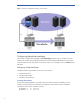
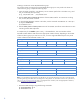
the primary storage is replicated to the secondary storage through these Continuous Access links. See Figure 3 for a pictorial representation of this setup. Figure 3. Configuring a VM into a package in Continentalclusters Complete the following steps to deploy an HP VM guest for disaster recovery in a Continentalclusters. 1. Create VM switches in all nodes of the primary cluster. 2. Configure replicated storage for VM in Continentalclusters. 3. Create the virtual storage over the replicated storage. 4.
7. Create VM switches in all nodes of the recovery cluster. 8. Prepare the replicated storage for use in the recovery cluster. 9. Create the virtual machine in all nodes of the recovery cluster. 10. Test the virtual guest OS in all nodes of the recovery cluster. 11. Resynchronize the replicated storage. 12. Package the HP VM in the primary and recovery cluster. 13. Create a Continentalclusters configuration with the VM packages. 14. Run the Continentalclusters monitoring daemon in the recovery cluster.
The VM Host ISO file that is used to install the OS into the guest is /var/os/hpvm.0505_OE.Gold1.iso. The guest virtual network device information consists of the following fields, separated by colons: • Network • Adapter-type—can be either lan or avio_lan • [Hardware-address] (optional)—formatted as bus,device,mac-addr. If you do not specify the hardware address, or a portion of it, the information is generated for you. HP recommends allowing Integrity VM to generate the hardware address.
Testing the virtual guest OS in all nodes of the recovery cluster Once the virtual machine is created, start the machine in Node3 of the recovery cluster. The machine will have the guest OS image that was installed in the primary cluster. However, because a static IP address was chosen at the primary cluster and the recovery cluster is in a different domain, the hostname and the network address for the guest HP-UX OS in the recovery cluster will impede networking.
Creating the Serviceguard package On the VM host, use the following procedure to create a Serviceguard package configuration file and control script (in case of legacy style package configuration) for the guest: 1. Create a Serviceguard package by running the hpvmsg_package script from the HP Serviceguard for Integrity VM Toolkit, which is installed in the /opt/cmcluster/toolkit/hpvm/ directory when you install Integrity VM. 2.
A. Creating a modular style Continentalclusters package To create a modular style Continentalclusters package, a modular Serviceguard package must first be created. Include a Continentalclusters module in the existing package configuration file and create a new package configuration file. Edit the newly created package configuration file to include physical replication-specific parameter values.
nodes. Complete the following procedure to configure a Metrocluster XP environment file on one of the nodes in the primary cluster. If you are using Metrocluster Continuous Access EVA or Metrocluster SRDF, refer to Appendix II for the detailed steps. For Metrocluster Continuous Access XP: 1. On one of the node in primary cluster, copy the data replication environment file “xpca.env” from the directory /etc/cmcluster/toolkit/SGCA to the package directory as _xpca.env. 2.
Related documentation The following related documents can be found at www.hp.
Appendix I 1. Sample legacy style package configuration file vmmetro.config for the example used in this white paper (a few parameters are listed; for others, defaults are assumed): # ********************************************************************** # © Copyright 2004-2006 Hewlett-Packard Development Company, L.P. # Confidential commercial computer software. Valid license required.
# The file where the output of the scripts is logged can be specified # via the SCRIPT_LOG_FILE parameter. If not set, script output is sent # to a file named by appending '.log' to the script path. # #SCRIPT_LOG_FILE RUN_SCRIPT RUN_SCRIPT_TIMEOUT HALT_SCRIPT HALT_SCRIPT_TIMEOUT /etc/cmcluster/vmmetro/vmmetro.cntl NO_TIMEOUT /etc/cmcluster/vmmetro/vmmetro.cntl NO_TIMEOUT ... # To configure a service, uncomment the following lines and # fill in the values for all of the keywords.
# #VXVM_DG[0]="" VXVM_DG[0]=vmdatadg … # Note: No environmental variables will be passed to the command, this # includes the PATH variable. Absolute path names are required for the # service command definition. Default shell is /usr/bin/sh. # #SERVICE_NAME[0]="" #SERVICE_CMD[0]="" #SERVICE_RESTART[0]="" SERVICE_NAME[0]="vmmetro" SERVICE_CMD[0]="/etc/cmcluster/vmmetro/hpvmkit.
For Metrocluster SRDF (vmmetro_srdf.env) AUTOSWAPR2=0 AUTOR1RWNL=0 AUTOR1UIP=1 AUTOR1RWSUSP=0 AUTOR2RWNL=1 AUTOR2WDNL=1 AUTOR2XXNL=0 CONSISTENCYGROUPS=0 DEVICE_GROUP="dgVM" PKGDIR="/etc/cmcluster/vmmetro" RETRY=60 RETRYTIME=5 CLUSTER_TYPE=”metro” RDF_MODE="sync" For Metrocluster Continuous Access EVA (vmmetro_caeva.
Appendix II Sample procedure for distributing a Metrocluster SRDF env file 1. Copy the environment file template /opt/cmcluster/toolkit/SGSRDF/srdf.env to the package directory /etc/cmcluster/vmmetro. If a legacy style package is created, rename it as the combination of the package control script file name (without the extension), concatenated with _srdf.env. For example, if the name of the package control script is vmmetro.cntl, then the name of this environment file would be vmmetro_srdf.env.
d) Set the WAIT_TIME variable to the timeout, in minutes, to wait for completion of the data merge from source to destination volume before starting up the package on the destination volume. If the wait time expires and merging is still in progress, the package will fail to start with an error that prevents restarting on any node in the cluster. e) Set the DR_GROUP_NAME variable to the name of the DR group used by this package. This DR group name is defined when the DR group is created.
For more information To read more about HP Serviceguard, HP Metrocluster, and HP Integrity Virtual Machines, go to: www.hp.com/go/hpux-hpvm-docs www.hp.com/go/hpux-serviceguard-docs Call to action To learn more about HP Integrity Virtual Machines and HP disaster recovery solutions, please contact your HP representative or visit: www.hp.com/go/integrityvm www.hp.com/go/serviceguard Share with colleagues © Copyright 2010, 2011 Hewlett-Packard Development Company, L.P.