
HP-UX SNAplus2 R7 General Information

Introducing SNAplus2
SNAplus2 Resources
Note
In some cases, the SNAplus2 Motif administration program simplifies the presentation of
resources (as compared to the command-line administration program). You do not need to
know what these differences are unless you intend to use both the Motif and command-line
programs. In this case, details can be found in
HP-UX SNAplus2 Administration Guide.
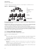
2.2.1 Node Resources
The following resources can be defined on individual nodes:
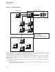
Ports
A port represents the local end of a communications link as a unique access point in the network.
Each port is associated with a specific link protocol, which can be any of the following:
• SDLC (synchronous data link control)
• X.25 QLLC (qualified logical link control)
• Token ring
• Ethernet
• FDDI (Fiber Distributed Data Interface)
• Enterprise Extender (HPR/IP)
More than one port can be associated with a particular link protocol.
In general, a port corresponds to a single physical access point, such as an adapter card. However, for some
link protocols (such as token ring), you can define multiple ports for a single adapter. In this case, the different
ports are distinguished by addresses such as the SAP number.
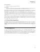
Link stations
A link station (LS) represents the logical path through the SNA network between the SNAplus2 local node
and a remote computer. The remote computer can be any of the following:
• A host computer
• A peer computer, with SNAplus2 and the remote computer communicating as equal partners (the typical
arrangement in an APPN network)
• A downstream computer that uses the SNAplus2 PU concentration or DLUR features to access a host
A link station is associated with a specific port; one or more link stations can be associated with each port.
Each dependent link station (to a host or to a downstream computer) has an associated PU (physical unit).
Because such PUs are associated with link stations, SNAplus2 does not treat them as separate resources; they
are configured as part of link station configuration, and started and stopped as part of starting and stopping
link stations.
If a remote node attempts to connect to the local node, and a suitable port is defined on the local node, but
no link station is defined that matches the address specified on the incoming call, SNAplus2 can define a
dynamically created link station for the duration of the connection.
In addition, SNAplus2 provides support for Rapid Transport Protocol (RTP), a High-Performance Routing
(HPR) feature of APPN. RTP enables you to reroute session traffic around route failures or congestion.
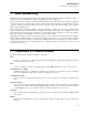
Connection networks (CNs)
In an APPN network, an end node is often connected only to a single network node, and each network node is
connected only to its nearest neighbors. Any node in the network can communicate with any other node, even
19