
A Conceptual Overview of iSCSI


5
4. Frame Construction
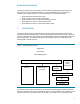
In section 2, “Protocol Layering”, an example of layering is provided that references the various
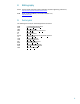
levels of encapsulation. An Ethernet frame is depicted in Figure 3.
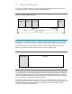
Figure 3. Layout of an Ethernet Frame
Each layer of the network stack, TCP, IP, and the Physical and Data Link layer, provides its own
encapsulation. A layer of encapsulation is added or removed as each network layer is traversed.
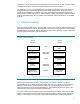
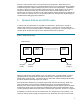
A TCP Data Segment will contain data obtained from the TCP Stream. iSCSI data in the TCP
Stream is formatted into Protocol Data Units (PDUs). Figure 4 depicts a PDU.
Figure 4. Protocol Data Unit (PDU)
There is nothing in the TCP Segment Header to indicate that the TCP Data Segment contains data
of a specific protocol. The TCP/IP definition does not prevent iSCSI PDUs and other network data
from being transmitted on the same network. Similarly, there is nothing that requires that they be
mixed, so a network administrator can determine whether an isolated subnet for iSCSI is necessary
or not. The decision is not dictated by the iSCSI protocol.
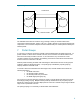
Because iSCSI PDUs are taken from the TCP Stream, they are treated like any other Stream data.
A single TCP Data Segment may contain one or more PDUs. A PDU is not required to begin or end
on a TCP Data Segment boundary and there is no requirement that a single PDU be wholly
contained in a single TCP Data Segment.
Ethernet
Header
IP
Header
TCP
Header
Ethernet
Trailer
TCP Segment
TCP Data Segment
IP Datagram
Ethernet Frame
PDU Header PDU Data