
HP-UX IPv6 Transition Mechanisms White Paper


9
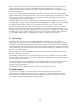
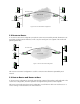
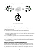
Figure 7 illustrates the topology of the organization after setting up the new branch office and the
required upgrades in the existing infrastructure.
IPv4 network
Dual-stack Host A1
Router R2
Host A2
Dual-stack Host A3
Host A5
Host A6
Dual-stack Router A4
Main officeBranch A
Figure 7: Organization topology with new branch office
Host M2
Router R1
Host M1
Dual-stack Host M3
Host M5
Host M6
Router M4
Host B6
Dual-stack Router R3
Host B2
Host B5
Host B4
Host B1
Router B3
New branch B (IPv6 network)
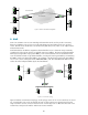
8.1 Access to Payroll Application in the Main Office
To enable employees in branch office B to access the payroll application running on server M3 in the
main office, a router-to-host tunnel configuration can be used. A router–to-host configured tunnel is setup
between router R3 and server M3. M3 is the endpoint for the tunnel from R3 to M3 and R3 is the
endpoint for tunnel from M3 to R3.
The communication between hosts in branch office B and server M3 is described below:
1. A host in branch office B sends an IPv6 packet with server M3 as the destination address.
2. The router R3 receives the outgoing IPv6 packet. Based on the tunnel information, it encapsulates the
IPv6 packet in an IPv4 packet with the source address set to IPv4 address of R3 and destination address
set to the IPv4 address of server M3.
3. The encapsulated packet is forwarded to server M3 using the IPv4 routing infrastructure. When M3
receives the packet, it decapsulates it and since it is also the final destination of the IPv6 packet, it sends
the packet up to the application.
4. When server M3 sends the response back, the IPv6 packet is encapsulated in IPv4 packet with the
source address set to the IPv4 address of M3 and the destination address set to IPv4 address of R3.
5. The encapsulated packet is received by router R3. R3 decapsulates the packet and forwards the IPv6
packet to its final destination.
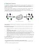
8.2 Access to Accounting Application in Branch Office A
To enable employees in the branch office B to access the accounting application running on server A1
and A3, a router-to-router tunnel configuration between router R3 and router A4 can be used. The router
A4 is the endpoint for the tunnel from R3 to A4 and R3 is the endpoint for the tunnel from A4 to R3.
The communication between nodes in branch office B and server A1 and A3 happens as described in
the previous section. The routers A4 and R3 will do the encapsulation and decapsulation.