
Split Trunking Support with HP Auto Port Aggregation
Switch(config-if-range)#channel-group 25 mode on
Switch(config-if-range)#exit
Switch(config)#
Switch(config)#interface range Gi2/0/13 - 14
Switch(config-if-range)#switchport mode access
Switch(config-if-range)#channel-group 25 mode on
Switch(config-if-range)#end
Switch#
On the server side, create the manual link aggregation lan900 on HP-UX 11i v3 using nwmgr as
follows:
# nwmgr –a –A mode=MANUAL –A links=3,4,6,7 –c lan900
Clearing the LACP link aggregate on the switch side
To delete the link aggregation, disable the LACP on all the ports used by the EtherChannel. This is
done by setting the channel-group mode back to the default value as follows:
Switch> enable
Switch#config terminal
Switch(config)#interface range Gi1/0/13 - 14
Switch(config-if-range)#default switchport mode
Switch(config-if-range)#no channel-group
Switch(config-if-range)#exit
Switch(config)#
Switch(config)#interface range Gi2/0/13 – 14
Switch(config-if-range)#default switchport mode
Switch(config-if-range)#no channel-group
Switch(config-if-range)#end
Switch#
On the server side, enter:
# lanadmin –X –c 901
Setting up Split Trunks on Nortel Switches
To create a split trunk (called a Split Multi-Link Trunk (SMLT) in the Nortel documentation), you must
configure all of the switches used by the LACP trunk with an interswitch trunk (IST). Having configured
the IST, the split multilink trunk is configured. By definition, two switches are used in the split trunk.
SMLT are supported on the Nortel 8000 Passport switches.
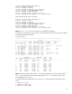
Example: Creating a four-port LACP SMLT trunk
This example creates an LACP SMLT using four 100 Base-T ports connected on two Nortel 8600
Passport switches. Two of the four ports are connected to switch 1 at ports 2/31 and 2/32. The other
two ports are connected to switch 2 also at ports 2/31 and 2/32. On the server side, switch 1 port
2/31 is connected to lan10, switch 1 port 2/32 to lan9, switch 2 port 2/31 to lan12, and switch
2 port 2/32 to lan11.
Four ports per switch are used for the ISTs at ports 3/6, 3/7, 4/6, and 4/7 on each switch. In the
following example, the vlan 1900 is used to pass the LACP protocol PDUs between the two
switches.
Step 1: Create the IST on both switches.
Set up the IST so that LACP protocol PDUs can be exchanged between the two switches.
Create the IST on switch 1 as follows:
9