
Split Trunking Support with HP Auto Port Aggregation
Examples
The following software and hardware components were used to produce the examples in this section:
• HPUX 11iv3 system running APA 11iv3 December 2007 release (AR0712)
• Cisco Switch Model 3750G-16TD with software version 12.2.25-SEE4.
• Nortel Switch Passport 8006 (software release 3.7.13.0)
• Nortel Switch Passport 8010 (software release 3.7.13.0)
Setting up Split Trunks on Cisco Switches
Split trunks (called cross-stack EtherChannels in Cisco documentation), are supported only on the
Cisco 3750 series switches. According to the Cisco 3750 configuration guide, cross-stack PAgP
EtherChannels are not supported. Manual and LACP mode cross-stack EtherChannels are supported.
To set up a switch stack, you must connect the 3750 switches to each other in a ring configuration
using cables connected to the Stackwise ports on the back of the switch. For information and setup
instructions, see the Cisco 3750 switch configuration guide.
After the switch stacking is enabled on all the member switches in the stack, you can view the switch
ports of all stack members from the master switch. In essence, the switch stack behaves like one
switch. The configuration of a cross-stack EtherChannel is no different from setting up an EtherChannel
on a single switch. A cross-stack EtherChannel consists of switch ports on more than one switch. See
the configuration guide for the Cisco 3750 switch on configuring manual and LACP type
EtherChannels.
On the HP-UX server side, use the lanadmin or nwmgr commands to create a Manual or LACP mode
link-aggregation as usual. For HP-UX 11i v3, use either the nwmgr or lanadmin commands to do
the configuration. For HP_UX 11i v2 or 11i v1, use lanadmin.
Example: Creating a four-port cross-stack LACP EtherChannel in active mode in a
two-switch stack, two ports per switch
This example creates an LACP EtherChannel using four gigabit switch ports in a two-switch stack. The
port mode for LACP is either active or passive. The port numbers are 13 and 14 on each switch. On
the server side, ports 3, 4, 6, and 7 are connected to switch ports Gi1/0/13, Gi1/0/14,
Gi2/0/13, and Gi2/0/14, respectively. Ports Gi1/0/13 and Gi1/0/14 are on switch 1;
Gi2/0/13 and Gi2/0/14 are on switch 2.
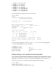
On the master switch (switch 1), define the LACP EtherChannel as follows:
Switch> enable
Switch#config terminal
Switch(config)#interface range Gi1/0/13 - 14
Switch(config-if-range)#switchport mode access
Switch(config-if-range)#channel-group 25 mode active
Switch(config-if-range)#exit
Switch(config)#
Switch(config)#interface range Gi2/0/13 - 14
Switch(config-if-range)#switchport mode access
Switch(config-if-range)#channel-group 25 mode active
Switch(config-if-range)#end
Switch#
This creates an EtherChannel with the LACP operational key value of 25. The ports actively send out
LACP PDUs to their link partners.
On the HP-UX server, create LACP link aggregate 901 (key=901) using ports 3, 4, 6, and 7 with the
following APA lanadmin commands:
7