
HP-UX Workload Manager overview


13
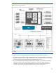
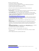
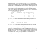
Figure 1. Process flow diagram of WLM
As shown in Figure 1, the main functional process flow for the WLM design is as follows:
1. Workloads (and/or workload groups) and their goal-based or shares-based SLOs are defined in
the WLM configuration file. The WLM configuration file also provides the path names for any data
collectors. WLM reads the configuration file and starts the data collectors.
2. For each application with a usage goal, WLM creates a controller. The controller is an internal
component of WLM. Each controller tracks its application’s actual CPU usage (utilization of
allocated CPU resources). No user-supplied metrics are required. The controller requests an
increase or decrease to the workload’s CPU allocation to achieve the usage goal.