
Veritas Storage Foundation 5.1 SP1 Cluster File System Installation Guide (5900-1510, April 2011)


#configure Links
#link tag-name device node-range link-type udp port MTU \
IP-address bcast-address
link link1 /dev/udp - udp 50000 - 192.1.2.2 192.1.2.255
link link2 /dev/udp - udp 50001 - 192.1.3.2 192.1.3.255
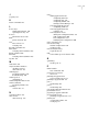
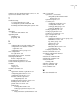
Sample configuration: links crossing IP routers
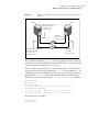
Figure L-2 depicts a typical configuration of links crossing an IP router employing
LLT over UDP. The illustration shows two nodes of a four-node cluster.
Figure L-2
A typical configuration of links crossing an IP router
Node0 on site
A
Node1 on site
B
UDP Endpoint /dev/udp
UDP Port = 50000
IP = 192.1.1.1
Link Tag = link1
UDP Endpoint /dev/udp
UDP Port = 50001
IP = 192.1.2.1
Link Tag = link2
/dev/udp
192.1.4.1
Link Tag = link2
/dev/udp
192.1.3.1
Link Tag = link1
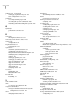
The configuration that the following /etc/llttab file represents for Node 1 has
links crossing IP routers. Notice that IP addresses are shown for each link on each
peer node. In this configuration broadcasts are disabled. Hence, the broadcast
address does not need to be set in the link command of the /etc/llttab file.
set-node Node1
set-cluster 1
link link1 /dev/udp - udp 50000 - 192.1.3.1 -
link link2 /dev/udp - udp 50001 - 192.1.4.1 -
#set address of each link for all peer nodes in the cluster
#format: set-addr node-id link tag-name address
set-addr 0 link1 192.1.1.1
set-addr 0 link2 192.1.2.1
set-addr 2 link1 192.1.5.2
set-addr 2 link2 192.1.6.2
Configuring LLT over UDP using IPv4
Manually configuring LLT over UDP using IPv4
496