
Veritas Storage Foundation 5.1 SP1 Cluster File System Installation Guide (5900-1510, April 2011)


In the vxfenmode file on the client nodes, vxfenmode is set to customized with
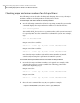
vxfen mechanism set to cps.
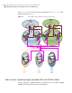
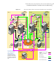
Figure I-1
Two unique client clusters served by 3 CP servers
NIC 1
Cluster -1
node 1
NIC 2
NIC 1
Cluster-1
node 2
NIC 2
Ethernet
Switch
Ethernet
Switch
NIC 1
Cluster -2
node 1
NIC 2
NIC 1
Cluster-2
node 2
NIC 2
Ethernet
Switch
Ethernet
Switch
NIC
CP Server 1
Ethernet
Switch
Intranet/Internet
Public network
CP Server 2
NIC
CP Server 3
NIC
NIC 3
NIC 3
NIC 3
NIC 3
VCS client
cluster
(UUID1)
SFHA client
cluster
(UUID2)
Single
node
VCS
cluster
hosting
CPS-1
Single
node
VCS
cluster
hosting
CPS-2
Single
node
VCS
cluster
hosting
CPS-3
/etc/VRTScps/db
/etc/VRTScps/db
/etc/VRTScps/db
vxcpserv
VIP 1
vxcpserv
VIP 2
vxcpserv
VIP 3
HBA
HBA
HBA
HBA
GigE
GigE
GigE
GigE
GigE
GigE
GigE
GigE
VLAN
Private
network
VLAN
Private
network
mycps1.company.com
mycps2.company.com
mycps3.company.com
vxfenmode= customized
vxfen_mechanism = cps
cps1=[mycps1.company.com]=14250
cps2=[mycps2company.com]=14250
cps3=[mycps3.company.com]=14250
vxfenmode= customized
vxfen_mechanism = cps
cps1=[mycps1.company.com]=14250
cps2=[mycps2company.com]=14250
cps3=[mycps3.company.com]=14250
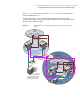
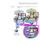
Client cluster served by highly available CPS and 2 SCSI-3 disks
Figure I-2 displays a configuration where a client cluster is served by one highly
available CP server and 2 local SCSI-3 LUNs (disks).
Sample SFCFS cluster setup diagrams for CP server-based I/O fencing
Configuration diagrams for setting up server-based I/O fencing
466