
STREAMS-UX Programmer's Guide (February 2007)


Multiplexing
Connecting and Disconnecting Multiplexor Configurations
Chapter 5
114
Connecting and Disconnecting Multiplexor Configurations
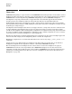
The STREAMS framework requires two additional qinit structures when managing a multiplexor. These
additional structures are specified in the multiplexors streamtab structure. A multiplexor is logically
partitioned into an upper-half and a lower-half. The upper-half uses the st_rdinit and st_wrinit qinit
structures specified in streamtab. The lower-half uses the st_muxrinit and st_muxwinit qinit structures
specified in streamtab. The st_muxrinit is the lower-half read-side qinit structure and the st_muxwinit is
the lower-half write-side qinit structure.
The multiplexor queue structures use the upper-half qinit structures from streamtab. The stream head of
the stream linked below the multiplexor uses the lower-half qinit structures. When a stream is linked below
the multiplexor, the qinit structures of the stream head are substituted by the lower-half qinit structures of
the multiplexor. This linkage allows multiplexors to switch messages between upper and lower streams.
When a message reaches the top of the lower stream, it is handled by the put and service procedures
specified in the lower-half qinit structures of the multiplexor.
To Create a Multiplexor Configuration
A multiplexor configuration is created as follows:
1. An open() call on the multiplexing driver creates the upper stream as in any other driver. open() uses
upper-half qinit structures from the multiplexor streamtab to create the driver queues. The
st_muxrinit and st_muxwinit fields of the streamtab are non-null but they are ignored by the open()
call. Any subsequent open() calls on this driver will create similar streams.
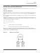
2. An open() on the device file will create the driver stream that we want to link under the multiplexor. The
driver for this stream is typically a device driver that is compatible with the multiplexor. See Figure 5-1
on page 111.
3. Push any modules that need to be pushed on the driver stream. The stream head queues still point to its
put and service procedures as specified in the stream head streamtab.
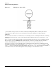
4. Connect the driver stream below the multiplexing stream by an I_LINK ioctl() call [See streamio(7)]. The
configuration now looks like Figure 5-2. The I_LINK on the multiplexor stream will modify the contents
of the stream head queues of the driver stream. These contents will now point to the lower-half
multiplexor's put and service procedures specified in st_muxrinit and st_muxwinit.
During this call, the stream head of the multiplexor stream sends an M_IOCTL message with ioc_cmd set
to I_LINK to the multiplexing driver. The M_DATA part of the M_IOCTL contains an linkblk structure. The
multiplexing driver stores the linkblk structure information in its private storage and returns an
M_IOCACK message. The l_index is returned to the user space process as muxid to request an I_UNLINK
later.
The linkblk structure contains following fields:
l_qtop
Is the multiplexor’s write queue.
l_qbot
Is the stream head write queue of the stream linked below multiplexor.
l_index
Is a unique (system wide) identifier for the link.