
Planning and Implementing VLANs with HP-UX


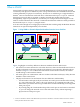
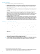
Table Of Contents
- Planning and Implementing VLANs with HP-UX
- Table of Contents
- About This Document
- What is VLAN?
- VLANs on HP-UX
- Features and Advantages
- Implementing VLANs on HP-UX
- Priority and Class of Service (CoS)
- IP ToS and 802.1p Conversion—End-to-End Class of Service
- Typical Customer Configurations
- Using HP-UX VLANs with HP Auto Port Aggregation (APA)
- Using HP-UX VLANs with HP Virtual Machines (HPVM)
- Future HP-UX VLAN Feature Additions
What is VLAN?
Virtual LAN (VLAN) technology allows network administrators to separate logical network
connectivity from physical connectivity. This concept is different from a traditional LAN in that
a LAN is limited by its physical connectivity. All users in a LAN belong to a single broadcast
domain
1
and can communicate with each other at the Data Link Layer or “Layer 2”. Network
managers have used LANs to segment a complex network into smaller units for better
manageability, improved performance, and security. For example network managers use one
LAN for each IP subnet in their network. Communication between subnets is made possible at
the Network Layer or “Layer 3”, using IP routers.
A VLAN can be thought of as a single physical network that can be logically divided into discrete
LANs that can operate independently of each other.
Figure 1 Using VLANs to Create Independent Broadcast Domains Across Switches
Blue VLAN
Green VLAN
Red VLAN
VLAN-aware
Switch
VLAN-aware
Switch
VLAN-aware
Switch
Figure 1 highlights several key differences between traditional LANs and VLANs.
• All switches are interconnected to each other. However, there are three different VLANs or
broadcast domains on the network. Physical isolation is not required to define broadcast
domains. If Figure 1 was a traditional LAN without VLAN-aware switches, all stations
would belong to one broadcast domain.
• All switch ports can communicate with one another at the Data Link Layer, if they become
members of the same VLAN.
• The physical location of an end station does not define its LAN boundary.
— An end station can be physically moved from one switch port to another without losing
its “view of the network”. That is, the set of stations it can communicate with at the
Data Link Layer remains the same, provided that its VLAN membership is also migrated
from port to port.
— By reconfiguring the VLAN membership of the switch port an end station is attached
to, you can change the network view of the end station easily, without requiring a
physical move from port to port.
1. A LAN is a broadcast domain at the Data Link Layer because a broadcast or multicast frame sent from a station is
seen by all other stations in its LAN.
What is VLAN? 7