
Planning and Implementing VLANs with HP-UX
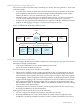
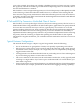
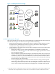
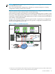
Table Of Contents
- Planning and Implementing VLANs with HP-UX
- Table of Contents
- About This Document
- What is VLAN?
- VLANs on HP-UX
- Features and Advantages
- Implementing VLANs on HP-UX
- Priority and Class of Service (CoS)
- IP ToS and 802.1p Conversion—End-to-End Class of Service
- Typical Customer Configurations
- Using HP-UX VLANs with HP Auto Port Aggregation (APA)
- Using HP-UX VLANs with HP Virtual Machines (HPVM)
- Future HP-UX VLAN Feature Additions
In the scenario illustrated in Figure 6, the peer-to-peer communication can be between:
• Two HPVM guests virtual network interfaces through the shared virtual switch.
For example, guests A and C (virtual switch ports 1 and 3 respectively) can communicate
with each other over the RED VLAN.
• An HPVM guest virtual network interface and the physical network interface on the local
HPVM host, through the virtual switch.
For example, guests A and C can communicate to the host VLAN interface, lan5000, over
the RED VLAN. Similarly, guest B can communicate with the host VLAN interface lan5001
over the BLUE VLAN.
• An HPVM guest virtual network interface and a remote node through the virtual switch,
the associated network interface on the HPVM host and the physical network
For example, guest A can communicate with client X over the RED VLAN. Similarly, guest
B can communicate with client Y over the BLUE VLAN.
Also note that the second virtual network interface on guest C (port 4) is connected to a virtual
switch port that is not configured for VLANs. Thus, it cannot communicate with either guest A
(over the RED VLAN) or with guest B (over the BLUE VLAN). However, it still can communicate
with client Z that is also not a member of any VLAN.
The HPVM system administrator can enforce the required isolation policies by configuring
appropriate VLAN membership for virtual switch ports. The HPVM system administrator
configures virtual switch ports for the same VLAN if communication between corresponding
guest interfaces is desired. Note that the VLAN membership rules on the physical network are
now extended to HPVM guests by virtue of a VLAN-aware HPVM virtual switch.
Since the VLAN-aware virtual switch extends the VLAN-aware network domain, it follows that
VLAN configuration of the HPVM virtual switch(es) must be consistent with the VLAN
configuration of the physical network and vice-versa for proper operation and enforcement of
policies. For example, if an HPVM guest is to communicate with a remote host over a VLAN,
both the HPVM virtual switch port for the guest and the physical switch port that connect the
physical interface that backs the virtual switch must be configured for the same VLAN.
Future HP-UX VLAN Feature Additions
HP is investing in the following areas for improvements to the HP-UX VLAN product.
• Generic VLAN Reservation Protocol (GVRP) and Automatic Configuration: GVRP is an
IEEE protocol that allows a switch or an end station to advertise its VLAN membership to
its link partner. Using this mechanism, we could develop a mechanism for dynamically
assigning VLAN membership to end stations, so that you don’t need to manually assign
VLAN IDs to each NIC on an end station.
• Stack support for 802.1p/Cos/QoS (multi-queues): HP is investigating methods for
implementing an end-to-end Class of Service or Quality of Service solution by improving
on priority mechanisms in the network stack and NICs. An important component of this
solution will be the 802.1p mechanism.
• Application-based VLAN: Application-based VLANs provide the most flexible way for
configuring VLANs—VLAN-aware applications determine the membership of the traffic
they generate. This mechanism opens up a number of interesting possibilities. For example,
a set of stations may negotiate a dynamically created VLAN for the purpose of carrying on
a short-term audio or videoconference.
• HP-UX VLAN implementation will be a key value addition to many exciting new technologies
in the horizon, such as iSCSI, 10-Gigabit Ethernet, and IPv6.
18