HP-UX VLAN Administrator's Guide HP-UX 11i Version 3 HP Part Number: 5991-6432 Published: February 2007 Edition: 1.
© Copyright 2007 Hewlett-Packard Development Company, L.P. Confidential computer software. Valid license from HP required for possession, use or copying. Consistent with FAR 12.211 and 12.212, Commercial Computer Software, Computer Software Documentation, and Technical Data for Commercial Items are licensed to the U.S. Government under vendor's standard commercial license. The information contained herein is subject to change without notice.
Table of Contents About This Document.........................................................................................................9 1 Introduction...................................................................................................................13 Overview of VLANs.................................................................................................................................13 What Is a VLAN?........................................................................
Editing the vlanconf File to Configure and Administer HP-UX VLANs....................47 Sample /etc/rc.config.d/vlanconf File.........................................................................................................47 Modifying the /etc/rc.config.d/vlanconf file................................................................................................48 5 Troubleshooting............................................................................................................
List of Figures 1-1 1-2 1-3 1-4 1-5 1-6 1-7 2-1 2-2 2-3 2-4 2-5 5-1 VLANs: Physical Versus Logical View..........................................................................................14 Using VLANs to Create Independent Broadcast Domains Across Switches................................15 IEEE 802.1Q VLAN Tag in Ethernet Frame...................................................................................17 VLANs Overlapping or Sharing the Same LAN Card Port......................................
List of Tables 1-1 1-2 1-3 1-4 1-5 3-1 Summary of VLAN Tagging Assignment.....................................................................................20 ToS to 802.1p User Priority Mappings ..........................................................................................22 HP-UX VLAN Priority Override Setting and Outbound IP Packet Priority Setting....................23 HP-UX VLAN ToS Override Setting and Inbound IP Packet Header ToS Setting........................
About This Document This document describes how to configure, administer, and troubleshoot HP-UX VLAN functionality. You can find the latest version of this document at the HP Technical Documentation website: http://www.docs.hp.com Intended Audience This document is intended for system and network administrators responsible for configuring and administering HP-UX Virtual LANs (VLANs). Administrators are expected to have knowledge of HP-UX and networking concepts, commands and configuration.
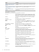
Chapter Description Chapter 3: “Using nwmgr to Configure This chapter explains how to administer HP-UX VLANs using the nwmgr and Administer HP-UX VLANs” command. (page 39) Chapter 4: “Editing the vlanconf File to Configure and Administer HP-UX VLANs” (page 47) This chapter explains how to configure and administer HP-UX VLANs by editing the /etc/rc.config.d/vlanconf file. Chapter 5: “Troubleshooting” (page 49) This chapter describes troubleshooting techniques and how to report a problem to HP.
Related Information The following man pages and white paper contain useful and related information: • • • • nwmgr_vlan(1M) vlan(7) nwmgr(1M) HP-UX VLAN: Planning and Implementing VLANs with HP-UX Publishing History The following table lists the publication history of this document: Document Manufacturing Part Operating System Supported Supported Product Version Publication Date Number 5991-6432 11i Version 3 B.11.31 February 2007 5991-0617 11i Version 2 September 2004 Update B.11.23.
1 Introduction This chapter provides an introduction to and technical overview of HP-UX Virtual LANs (VLANs).
Figure 1-1 VLANs: Physical Versus Logical View End Users Switches Servers Internetwork Router LAN 2 Physical View Marketing VLAN Internetwork Router Engineering VLAN Manufacturing VLAN Logical View VLANs isolate broadcast and multicast traffic by determining which destinations receive that traffic, thereby making better use of switch and end-station resources. With VLANs, broadcasts and multicasts go only to the intended nodes in the virtual LAN.
Figure 1-2 Using VLANs to Create Independent Broadcast Domains Across Switches VLAN-Aware Switches Network switches and end stations that know about VLANs are said to be VLAN aware. Network switches and end stations that can interpret VLAN tags are said to be VLAN tag aware. To implement a VLAN in your network, you must use at least VLAN-aware switches. To understand how logical partitioning of a LAN infrastructure is done using VLAN, keep in mind the fundamental operation of a traditional switched LAN.
You can configure VLAN-aware switches to add ports to a VLAN group or groups. VLAN-aware switches maintain two simple, related tables: a list of ports that belong to each VLAN enabled on the switch, and the set of VLANs enabled on each port. Several varieties of VLAN-aware switches are available: • • • The most basic VLAN-aware switches support port-based VLANs. In a port-based VLAN, the switch port on which the frame arrived determines the VLAN membership of the frame.
Figure 1-3 IEEE 802.1Q VLAN Tag in Ethernet Frame 4 Bytes Destination Address Source Address 2 Bytes Tag Protocol ID 802.1Q VLAN Tag Type/Len Data Frame Check 2 Bytes (Tag Control Information) User Priority (3 Bits) Canonical Format Indicator (1 Bit) VLAN ID (12 Bits) Figure 1-4 VLANs Overlapping or Sharing the Same LAN Card Port Server Run Attn.
Switches that implement only port-based VLAN can support only one VLAN per port. However, if they are tag aware (also called Q compliant), they can support multiple VLANs per port— one untagged VLAN and multiple tagged VLANs. If a frame does not have an explicit VLAN tag, it is automatically assigned the untagged VLAN ID or the default VLAN ID. An inbound frame that is tagged has its VLAN ID in the frame header.
1. Determine the network topology affected. Either draw the affected network topology or list it. Include all affected end stations. See “Network Requirements” (page 19) for key network requirements related to setting up VLANs. 2. Define the VLANs. In accordance with your requirements, determine which systems belong to which logical groups. See “Common VLAN Usage Scenarios ” (page 18) for common types of usage scenarios for VLANs. 3. Assign VLAN IDs to each VLAN interface.
Configuring VLANs on the Switch IEEE 802.1Q-compliant devices can coexist with legacy and untagged VLANs on the same networks. However, legacy and untagged VLANs require a separate link, whereas the 802.1Q-tagged VLANs can combine several VLANs into one link (see Figure 1-6). On 802.1Q-compliant devices, separate ports (configured as untagged) must be used to connect separate VLANs to non-802.1Q devices.
The usage type of the HP-UX VLAN configured on a NIC port depends on how you create and configure the VLAN interfaces. Here are some examples: • • • For a port-based VLAN: You create just one VLAN interface on a given NIC port. All protocols and applications use this VLAN interface's VPPA to transmit data traffic. Therefore, all frames transmitted by that NIC port are tagged with the VLAN ID of that VLAN interface.
Priority is a field in the VLAN tag portion of the frame header. ToS is part of the IP precedence field in the IP header. Switches can use the 802.1p priority. Switches ignore ToS; routers can use it. In HP-UX, you can specify a 3-bit priority encoding (resulting in eight possible values) for each VLAN configured on a NIC port. HP-UX VLANs conform to the IEEE 802.1p standard for priority. The VLAN tag carries this value to all the switches on the route.
For IP traffic, 802.1p priority and ToS values in the HP-UX VLAN tag are determined as follows: • • The 802.1p priority value in the HP-UX VLAN tag of the outbound IP packet is determined as described in Table 1-3. The ToS value of an inbound IP packet header is determined as described in Table 1-4.
• • • HP-UX VLANs do not require you to rewrite applications, install new hardware, or recable. They are also compatible with HP Serviceguard as well as with HP online addition and replacement (OLAR) capabilities. You can create, modify, and delete HP-UX VLANs without rebooting the system. HP-UX VLANs are interoperable with non-VLAN-aware devices, such as servers or bridges, that do not transmit or receive tagged packets.
For information on using nwmgr to administer HP-UX VLANs, see Chapter 3 (page 39). For detailed information about using nwmgr to administer HP-UX VLANs, see nwmgr(1M) and nwmgr_vlan(1M). • Manually edit the /etc/rc.config.d/vlanconf file. Though not generally recommended, another method for administering HP-UX VLANs on your system is to edit the /etc/rc.config.d/vlanconf file. Changes made using this method do not take effect until the next reboot.
• • Direct attributes: Direct attributes are configurable attributes specific to the VLAN interface. Derived attributes: Derived attributes are inherited attributes of the physical interface on which the VLAN is created. • Associated IP attributes: Associated IP attributes are IP attributes associated with the VLAN interface. The following sections describe each of these types of attributes.
Associated IP Attributes HP-UX VLAN interfaces have IP attributes assigned to them the same way that physical interfaces do. The following IP attributes are associated with HP-UX VLAN interfaces when an IP address has been assigned to the HP-UX VLAN interface.
Unsupported Functionality HP-UX VLANs do not support the following functionality: • • The GARP VLAN registration protocol (GVRP) is currently not supported. HP-UX VLANs cannot send GVRP messages or interpret them. HP-UX VLANs do not operate on the following: — HP-UX 10.20, 11.0, and 11.20. — FDDI, Token Ring, ATM, 100VG, EISA, HyperFabric, and HP-PB LAN cards.
2 Using HP SMH to Configure and Administer HP-UX VLANs This chapter summarizes how to configure and administer HP-UX VLANs using HP SMH. It addresses the following topics: • “Overview” (page 29) • “Navigating HP SMH” (page 29) • “Adding a VLAN Interface” (page 33) • “Modifying a VLAN Interface” (page 36) • “Deleting a VLAN Interface” (page 37) Overview As of this release, the HP-UX system administration tool for single-server administration is the HP System Management Homepage (HP SMH).
IMPORTANT: Use the Cancel button rather than the browser navigation buttons when using HP SMH. • Help buttons are available for all operations. Navigating to VLANs Use the following procedure to invoke HP SMH and navigate to the main VLAN configuration page: 1. Enter the following: # /usr/sbin/smh Alternatively, to launch HP SMH from a browser window, enter: http://name_of_system_to_administer:2301 If the DISPLAY environment variable is set, HP SMH opens in the default web browser.
NOTE: This chapter provides an overview of the configuration process. Consult the online help to obtain specific information about available actions and field descriptions.
TUI Example When HP SMH is invoked and the DISPLAY environment variable is not set, HP SMH displays a TUI. .Figure 2-2 illustrates the HP SMH TUI main VLAN configuration screen. Navigate as needed through the screens to perform the desired VLAN-related administrative actions.
Adding a VLAN Interface This section provides an overview of how to add a VLAN interface using the SMH Network Interfaces Configuration tool. 1. From the main VLAN configuration page, shown in Figure 2-1 (page 31), select Add VLAN to open a page that displays all interfaces on which a VLAN can be added. The Add VLAN Interface page (Figure 2-3) consists of a table that displays VLAN-capable interfaces and fields for entering attribute values for the VLAN interface being created.
3. Enter a VLAN ID. The VLAN ID must be unique within the related interface. This field is required. Valid values: 0 to 4094, inclusive. IMPORTANT: You must assign a VLAN ID to each VLAN interface. Verify that the assignments are consistent across end stations and switches; otherwise, the stations cannot communicate with each other. 4. Enter a VLAN name, or accept the default value. (Default: An empty string, which displays as UNNAMED) The VLAN name must be unique within the related interface.
Current Applies the Add VLAN changes to the current configuration. This option is always selected; it cannot be unselected. NOTE: Saved Changes are not maintained across reboots unless you select Saved. Saves the information to etc/rc.config.d/vlanconf, which maintains the changes across reboots. 11. Click OK to add the VLAN interface. This returns you to the page from which you selected the Add VLAN action (either the NIC or VLAN main page).
Modifying a VLAN Interface After you configure a VLAN, you can modify its properties whether or not it has an IP address configured. On the main VLAN page, select a configured VLAN interface, and select View/Modify VLAN. This opens the View/Modify VLAN page, as shown in Figure 2-4. Modify fields as needed. The fields (except for VPPA, which can not be modified) are the same as those discussed in the section “Adding a VLAN Interface” (page 41).
Deleting a VLAN Interface The following procedure describes how to delete a VLAN interface. 1. 2. On the main VLAN page, select a configured VLAN interface, and select Delete VLAN. This opens the Delete VLAN Interface confirmation page, as shown in Figure 2-5. If the Critical Resource Analysis (CRA) report passes, delete the selected VLAN interface by clicking OK.
3 Using nwmgr to Configure and Administer HP-UX VLANs As of this release, a new command, nwmgr, is provided for managing all LAN-based network interfaces. The nwmgr command offers a superset of the functionality provided by the lanscan, lanadmin, and linkloop commands, which are deprecated in this release and will be obsoleted in a future HP-UX release.
nwmgr --diag [link] -A dest=[,pktsize=,timeout=] [--it ] -c lan nwmgr: Operational Overview This section briefly summarizes the operational parameters of nwmgr. It lists the operations available as well as some of the options available on those operations.
Adding a VLAN Interface Assume that your system has physical interfaces configured as shown by the following output: # nwmgr Name/ ClassInstance ============== lan0 lan1 lan2 Interface State ========= UP DOWN UP Station Address ============== 0x00306E4B08F9 0x00306E5FF044 0x00306E5FF045 Subsystem ======== igelan btlan btlan Interface Related Type Interface ============== ========= 1000Base-T 100Base-TX 100Base-TX To use nwmgr to configure a VPPA with VLAN ID = 454 and a priority = 6 on lan0, enter: # n
A VLAN interface (lan5000) displays in nwmgr output the same as a physical interface. VPPAs are identified by the string vlanx in the Name/ClassInstance field, where 5000 <= x < 9000 and is unique per VPPA.
# nwmgr -c lan5000 VLAN Interface Name ============= lan5000 Related Interface ========= lan0 VLAN ID Pri Pri ToS Override Level ===== ==== ========== ==== 53 3 CONF_PRI 0 Tos Name Override Level ========== ================ IP_HEADER UNNAMED The changes are visible in the display output. Deleting a VLAN Interface Before attempting to delete a VLAN interface, ensure that no applications or upper layer protocols are active on the VLAN interface.
To delete VLAN interface lan5000, enter: # nwmgr -d -c lan5000 For example: # nwmgr -d -c lan5000 Successfully deleted the VLAN Interface lan5000. To delete a VLAN interface with an IP address assigned, you must first delete the IP address. You can do this by using the ifconfig command with the -unplumb option. See ifconfig(1M) for more information. You can also use the HP SMH Network Interfaces Configuration tool to delete IP attributes. See Chapter 2 (page 29) for more information.
Example: Performing a Persistent Store/Save to vlanconf file (-- sa --fr cu) When --sa --fr cu is specified, nwmgr saves changes made with the set operation (-s |--set) to the /etc/rc.config.d/vlanconf file for persistence across reboots. If the --saved option is not specified, changes made using the --set operation are not retained across reboots.
4 Editing the vlanconf File to Configure and Administer HP-UX VLANs This chapter provides an overview of how to administer HP-UX VLAN interfaces by editing the configuration file for VLANs , /etc/rc.config.d/vlanconf, using a text editor such as vi. Changes made by editing the vlanconf file do not take effect until the system is rebooted. Sample /etc/rc.config.d/vlanconf File The following example displays the format of the /etc/rc.config.d/vlanconf file.
# VLAN_VPPA[0]= Modifying the /etc/rc.config.d/vlanconf file The following example illustrates the required lines to add to the /etc/rc.config.
5 Troubleshooting This chapter provides information for troubleshooting HP-UX VLANs. It addresses the following topics: • “Link-Level : Connectivity Test” (page 49) • “NetTL Trace and Log of VLANs” (page 52) • “Additional Information” (page 54) • “Reporting Problems to HP” (page 54) Link-Level : Connectivity Test Test link-level communications between local and remote hosts using the nwmgr command. The local interface should be a VPPA, that is, a PPA corresponding to a VLAN interface.
Flowchart: Connectivity Test The following flowchart and procedure describe the process to determine, at the link-level, if the local and remote VLAN interfaces can successfully communicate. Figure 5-1 Flowchart: Connectivity Test Connectivity Test 1 2 Execute nwmgr --diag ...
Procedure : Connectivity Test This section describes how to step through the process illustrated in Figure 5-1. NOTE: This process assumes the local VLAN interface exists, is up, and that a connectivity test to the local host itself passes. To verify the local VLAN interface, use the nwmgr command to display detailed information about VLAN interfaces. Enter: # nwmgr -S vlan -v Examine the output to verify that the VLAN ID is as expected and that the interface state is UP.
NetTL Trace and Log of VLANs You can use the nettl tool to troubleshoot VLANs. When using nettl for tracing and logging VLANs, keep in mind the following: tracing: When tracing traffic on a VLAN interface (including traffic over link aggregates or failover groups), you must enable nettl tracing on the driver that owns the VLAN (for example iether), not on the VLAN subsystem.
^^^^^^^^^^^^^^100BT/Gigabit Ethernet LAN/9000 Networking^^^^^^^^^^^^^^^ Timestamp : Wed Nov 07 PST 2006 11:08:03.961449 Process ID : [ICS] Subsystem : GELAN User ID ( UID ) : -1 Trace Kind : PDU IN TRACE Device ID : 1 Path ID : -1 Connection ID : 0 Location : 00123 ~~~~~~~~~~~~~~~~~~~~~~~~~~~~~~~~~~~~~~~~~~~~~~~~~~~~~~~~~~~~~~~~~~~~~~~~ Received 1480 bytes via Ethernet Wed Nov 07 11:08:03.
Additional Information Keep in mind the following information when troubleshooting HP-UX VLANs: • • • All devices in a VLAN's data path must be VLAN aware (must understand VLAN membership and formats). On a switch or end station, all the frames for a specific VLAN must be either tagged or untagged. Promiscuous-mode characteristics: — Only one stream can run in the unbound promiscuous mode per physical interface and all the VLAN interfaces created over it.
Glossary This glossary provides definitions for common terms relevant to HP-UX VLANs. 1000Base-SX A Gigabit Ethernet (1000-Mb/s) communication method for Ethernet LANs designed to operate over two multimode fiber cables, as specified in IEEE 802.3z/D.50-1988. 1000Base-T A Gigabit Ethernet (1000-Mb/s) communication method for Ethernet LANs designed to operate over Category 5, 5e, or 6 unshielded twisted pair (UTP) cabling, as specified in the IEEE 802.3ab standards.
device class A logical grouping of similar devices. For example, Ethernet, Token Ring, and FDDI network interface cards all provide LAN connectivity and are in the same device class. directly connected network The network to which a host or node is directly connected. Also referred to as a local network. DLPI Data Link Provider Interface. An industry-standard definition for message communications to STREAMS-based network interface drivers.
hexadecimal values are separated by colons. Leading zeros within a 4-digit group can be omitted. For example, 2001:db8:0:0:0:0:1111:2222 is a valid IPv6 address. An address can contain one set of double colons (::), which indicates multiple groups of 16 bits of zeros, for example, 2001:db8::1111:2222. LAN Local area network.
priority A field in the VLAN tag portion of the frame header. Some switch vendors have implemented a priority mechanism that acts on this 3-bit priority encoded in the VLAN tag to provide rudimentary Class of Service (CoS). See also 802.1p. protocol A specification for communicating between devices, including the format and processing of messages. QoS Quality of Service. The ability to provide guarantees for data transfer - for example, latency, throughput, and discard priority.
VPPA Virtual interfaces that you create dynamically (using nwmgr or HP SMH). The interfaces are virtual because they do not have a unique hardware instance. A virtual PPA is the PPA associated with a VLAN.
Index A D adding VLAN interfaces, 25 nwmgr, 41 SMH, 33 administering VLANs attributes, 26 available methods, 24 editing vlanconf file, 47 nwmgr, 9, 24, 39, 40, 41 SMH, 24, 30 APA VLAN over APA, 9, 23 attributes of VLANs associated IP attributes, 27 derived attributes interface state, 26 MAC address, 26 MTU, 26 speed/duplex, 26 priority, 21, 22, 26, 34, 42 priority override level, 22, 23, 26, 34 ToS, 21, 26, 34 ToS override level, 22, 23, 26, 34 VLAN ID, 15, 19, 26, 34 VLAN Name, 26, 34 VPPA, 21, 26, 34 d
monitoring statistics, 25 HP system, 28 installation, 28 OS, 28 patches, 28 N nettl logging example, 53 tracing example, 52 troubleshooting VLANs, 52 Network Interfaces Configuration tool, 30 network planning, 18 network requirements, 19 nwmgr adding VLAN interfaces, 40, 41 administering VLANs, 9, 24 comparing to lanadmin, linkloop, 40 configuring VLANs, 9, 24 deleting VLAN interfaces, 40, 43 diagnosing VLAN interfaces (connectivity), 40 displaying VLAN interfaces, 40, 41, 42 help option, 40 modifying VLA
nwmgr, 40 VLAN conceptual overview, 13–20 features, 23 trunking, 18 usage scenarios, 18 VLAN ID 0, 26 VLAN ID attribute, 15, 19, 26, 34 VLAN Name attribute, 26, 34 VLAN over APA, 9, 23 VLAN properties displaying, 41, 42 VLAN tagging, 16–18, 20 explicit, 15, 16 VLAN type IP subnet-based, 18, 21 port-based, 18, 21 protocol-based, 18, 21 VLAN-aware switches, 15–16 vlanconf file (see /etc/rc.config.