
HP-UX Routing Services Administrator's Guide HP-UX 11i v2, HP-UX 11i v3 (B2355-91153, November 2011)


mrouted structures routing information in the form of a pruned broadcast delivery tree that contains
routing information. mrouted structures routing information only to those subnets that have members
of the destination multicast group. In other words, each router determines which of its virtual network
interfaces are in the shortest path tree. In this way, DVMRP can determine if an IP multicast datagram
needs to be forwarded. Without such a feature, the network bandwidth can easily be saturated
with the forwarding of unnecessary datagrams.
Because DVMRP routes only multicast datagrams, you must handle routing of unicast or broadcast
datagrams using a separate routing process.
To support multicasting across subnets that do not support IP multicasting, DVMRP provides a
mechanism called tunnelling. Tunnelling forms a virtual point-to-point link between pairs of mrouted
routers by encapsulating the multicast IP datagram within a standard IP unicast datagram using
the IP-in-IP protocol (IP protocol number 4). This unicast datagram, containing the multicast datagram,
is then routed through the intervening routers and subnets. When the unicast datagram reaches
the tunnel destination, which is another mrouted router, the unicast datagram is stripped away
and the mrouted daemon forwards the multicast datagram to its destinations.
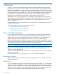
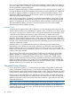
Figure 1 shows a tunnel formed between a pair of mrouted routers.
Figure 1 Tunnel Made with mrouted Routers
In this figure, the mrouted router R1 receives a multicast packet from node M. Because R1 is
configured as one end of a tunnel, R1 encapsulates the IP multicast packet in a standard unicast
IP packet addressed to the mrouted router R2. The packet, now treated as a normal IP packet,
is sent through the intervening nonmulticast network to R2. R2 receives the packet and removes
the outer IP header, thereby restoring the original multicast packet. R2 then forwards the multicast
packet through its network interface to node N.
IP Multicast Addresses
An IP Internet address can be either a 32-bit or a 128-bit address. Each host on the Internet is
assigned a unique IP address. There are four classes of IP addresses: Class A, Class B, Class C,
and Class D. Class D IP addresses are identified as IP multicast addresses. Class A, Class B, and
Class C IP addresses are composed of two parts: a network ID (netid) and a host ID (hostid). Class
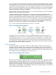
D IP addresses are structured differently, as shown in Figure 2 .
Figure 2 Class D IP Multicast Address Format
The first 4 bits (0 through 3) identify the address as a multicast address. Bits 4 through 31 identify
the multicast group. Multicast addresses are in the range 224.0.0.0 through 239.255.255.255.
Addresses 224.0.0.0 through 224.0.0.255 are reserved, and address 224.0.0.1 is permanently
assigned to the all hosts group. The all hosts group is used to reach all the hosts on a local network
that participate in IP multicasting. The addresses of other permanent multicast groups are published
in RFC 1060 (Assigned Numbers, March 1990).
The mrouted Routing Daemon 9