
HP-UX Routing Services Administrator's Guide HP-UX 11i v2, HP-UX 11i v3 (B2355-91153, November 2011)

An area border router advertises a default route in the stub area as the summary of all the IP
destinations that are reachable outside the AS. Summary link advertisements (routes to destinations
outside the area but within the AS) are still sent into the stub area.
The stub statement specifies that the area is a stub area. You can optionally define a cost clause
to specify the cost associated with the default route that is advertised in the stub area.
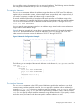
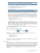
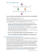
Figure 12 shows an example of an area border router that is connected to area 0.0.0.2 through
interface 193.2.1.20. Because all traffic in and out of the area 0.0.0.2 must pass through router
A, it is not necessary for the area’s internal routers, such as router B, to receive inter-area routing
information.
Figure 12 Area Border Router Configuration Example
The following is an example of the stub area definition in the router’s /etc/gated.conf file:
OSPF yes {
area 0.0.0.2 {
stub cost 5 ;
networks {
193.2.1.16 mask 0xfffffff0 ;
} ;
interface 193.2.1.20 nonbroadcast cost 5 {
enable ;
routers {
193.2.1.17 eligible ;
} ;
priority 5 ;
hellointerval 5 ;
routerdeadinterval 20 ;
retransmitinterval 10 ;
pollinterval 20 ;
} ;
} ;
} ;
Defining Backbones
The OSPF backbone distributes routing information between areas. You can define backbones
with the same statements and clauses as areas. You need not define the stub statement for a
backbone. The backbone statement is used to define a router as a backbone router. If an OSPF
internal or area boarder router is also a backbone router, the backbone statement must follow
the area statements in the /etc/gated.conf file. Whenever you configure an area border
router (a router connected to multiple areas), you must provide the backbone.
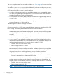
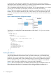
Figure 13 shows an example of two area border routers that form part of a backbone. Router A
has interfaces to both area 0.0.0.1 and area 0.0.0.2, while router B has interfaces to areas
0.0.0.3 and 0.0.0.4. Router A is connected to router B through interface 15.13.115.156.
36 Configuring gated