
HP-UX Routing Services Administrator's Guide HP-UX 11i v2, HP-UX 11i v3 (B2355-91153, November 2011)
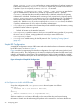
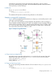
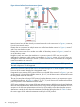
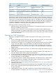

Table 2 Types of Link State Advertisements
Flooded ThroughoutOriginated ByContentType
AreaInternal and area border
routers
Router’s links to areaRouter link
AreaDesignated routerList of routers attached to networkNetwork link
AreaArea border routerRoutes to destinations outside area
but within AS
Summary link
ASAS boundary routerRoutes to destinations outside ASAS external link
AS boundary routers exchange routing information with routers in other autonomous systems. An
AS boundary router can be an area border router or an internal router. It can also be a backbone
router, but it is not required that an AS boundary router be a backbone router. An AS boundary
router learns about routes other than its attached AS through exchanges with other routing protocols
or through configuration information. Each AS boundary router calculates paths to destinations
outside of its attached AS. It then advertises these paths to all routers in its AS.
Following are the two levels of routing in an AS:
• Intra-area routing, where the source and destination of a packet both reside in the same area.
Routing is handled by internal routers.
• Inter-area routing, where the source and destination of a packet reside in different areas.
Packets travel through an intra-area route from the source to an area border router, then travel
an inter-area route on a backbone path between areas. Finally, they travel another intra-area
route to the destination.
Planning Your OSPF Configuration
Following is a suggested sequence of steps in planning the OSPF routing in your autonomous
system:
1. If your AS exchanges routing information with other autonomous systems, you need to obtain
a unique AS number from the Internet Assigned Numbers Authority.
2. Partition the AS into areas. You can partition any interconnected networks into lists of address
ranges, with each address range represented as an address-mask pair. The area border
routers summarize the area content for each address range and distribute the summaries to
the backbone. See “The networks Statement” (page 31) for more information on specifying
address ranges.
3. Identify the internal routers for each area. An internal router configuration contains only one
area definition.
4. Identify the area border routers and the areas to which they interface. The configuration for
each area border router contains multiple area definitions.
5. For each router, determine the interface type for each area. Router interfaces can be multicast,
non-broadcast multi-access (NBMA), or point-to-point. See “The interface Statement” (page 31)
for more information on router interfaces.
6. For multi-access networks, identify a designated router. For NBMA networks, several routers
can be designated router candidates. Designated routers are specified in the interface
definitions (see “The interface Statement” (page 31)).
7. You must decide if you want to assign a cost to each interface. See “Cost” (page 38) for more
information about costs.
8. Designate stub areas. AS external link advertisements are propagated to every router in every
area in an AS, except for routers in the configured stub areas. See “Stub Areas” (page 35)
for more information
9. Identify backbone routers. The router configuration contains a backbone definition and a
virtual link definition, if necessary. See “Defining Backbones” (page 36) for more information
Configuring the OSPF Protocol 29