
HP-UX LAN Administrator's Guide (Feburary 2007)

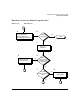
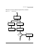
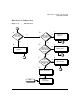
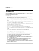
Table Of Contents
- About This Document
- 1 New for the HP-UX 11i v3 Release
- 2 Installing HP-UX LAN
- 3 Configuring HP-UX LAN Using SAM
- 4 Manually Installing and Configuring HP-UX LAN
- 5 Troubleshooting HP-UX LAN
- Troubleshooting Overview
- Troubleshooting Q & A
- LAN Interface Card Statistics
- 100Base-T Checklist
- Diagnostic Flowcharts
- Flowchart 1: Configuration Test
- Flowchart 2: Configuration Test continued
- Flowchart 3: Configuration Test continued
- Flowchart 4: Network Level Loopback Test
- Flowchart 5: Network Level Loopback Test continued
- Flowchart 6: Transport Level Loopback Test (using Internet Services)
- Flowchart 7: Link Level Loopback Test
- Flowchart 8: LAN Connections Test
- Flowchart 9: Gateway Remote Loopback Test
- Flowchart 10: Gateway Remote Loopback Test continued
- Flowchart 11: Subnet Test
- 6 LAN Resources
- 7 Network Addressing
- Overview of Network Addressing Schemes
- Networking Terminology
- Network Addresses and Node Names
- Internet Addresses
- Subnet Addresses
- Configuring Gateways on Fixed-Length Subnets
- Variable-Length Subnet Addressing
- Configuring Gateways on Variable-Length Subnets
- Configuring Gateways on Supernets
- IP Multicast Addresses
- Virtual IP (VIP) Addresses
- CIDR - Classless Inter-Domain Routing
- 8 LAN Device and Interface Terminology

DRAFT COPY Troubleshooting HP-UX LAN
Diagnostic Flowcharts
Chapter 5 75
Flowchart 8 Procedures
A. Thick or thin cabling? If your network cabling is the thicker coaxial cabling,
continue in the direction marked “Thick Coax.” If your network cabling is
the ThinLAN cabling, continue in the direction marked “ThinLAN.”
A1. RJ45 Adapter? Verify LEDs. Network Activity and Link Status LED
displays: Link Status LED is lit GREEN for a valid link. Network Activity
LED is lit AMBER color for both 10 Mbps and 100Mbps. Sometime Link
Status LED is not lit up at 10 Mbps mode.
A2. Card seated securely? Check adapter installation, reset and reseat adapter.
Check for incorrect or faulty network cable or connector. Ensure settings for
switch and adapter are the same.
B. Check: AUI solidly connected to LAN card. Make sure the AUI cable is
solidly connected to the LAN card. If the AUI cable is not connected, turn off
the power to the computer before you connect it.
C. Check: ThinLAN cable terminated at both ends. Make sure the backbone
cable is terminated at both ends.
D. Check: BNC T-connectors secure. Make sure each BNC T-connector is
securely attached to a BNC connector on the ThinLAN cable and that no
intervening cable is between the MAU and the T-connector.
E. Check: ThinLAN cable grounded in only one place. Make sure the ThinLAN
cable is grounded in only one place.
F. Problem solved? If so, stop. If you still have a problem after working through
this flowchart, you may have a failed LAN card, an incorrect jumper setting
on the LAN card, or a problem with the transmit or receive function of the
MAU. Contact your HP representative for help. Be prepared to discuss the
problem as described in “Contacting Your HP Representative” at the end of
this chapter.
G. Check: AUI solidly connected to MAU and LAN card. Make sure the AUI
cable is solidly connected to the MAU and the LAN card. If the AUI cable is
not connected, turn off the power to the computer before you connect it.
H. Check: Backbone cable terminated at both ends. Make sure the backbone
cable is terminated at both ends.
I. Check: MAU tapped securely into cable. Make sure the MAU is tapped
securely into the backbone cable.
J. Check: Splices and Taps. Make sure all splices and taps are secure.