
HP-UX LAN Administrator's Guide (Feburary 2007)
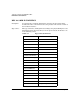
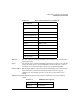
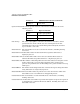

Table Of Contents
- About This Document
- 1 New for the HP-UX 11i v3 Release
- 2 Installing HP-UX LAN
- 3 Configuring HP-UX LAN Using SAM
- 4 Manually Installing and Configuring HP-UX LAN
- 5 Troubleshooting HP-UX LAN
- Troubleshooting Overview
- Troubleshooting Q & A
- LAN Interface Card Statistics
- 100Base-T Checklist
- Diagnostic Flowcharts
- Flowchart 1: Configuration Test
- Flowchart 2: Configuration Test continued
- Flowchart 3: Configuration Test continued
- Flowchart 4: Network Level Loopback Test
- Flowchart 5: Network Level Loopback Test continued
- Flowchart 6: Transport Level Loopback Test (using Internet Services)
- Flowchart 7: Link Level Loopback Test
- Flowchart 8: LAN Connections Test
- Flowchart 9: Gateway Remote Loopback Test
- Flowchart 10: Gateway Remote Loopback Test continued
- Flowchart 11: Subnet Test
- 6 LAN Resources
- 7 Network Addressing
- Overview of Network Addressing Schemes
- Networking Terminology
- Network Addresses and Node Names
- Internet Addresses
- Subnet Addresses
- Configuring Gateways on Fixed-Length Subnets
- Variable-Length Subnet Addressing
- Configuring Gateways on Variable-Length Subnets
- Configuring Gateways on Supernets
- IP Multicast Addresses
- Virtual IP (VIP) Addresses
- CIDR - Classless Inter-Domain Routing
- 8 LAN Device and Interface Terminology

DRAFT COPY Troubleshooting HP-UX LAN
100Base-T Checklist
Chapter 5 51
100Base-T Checklist
In case of trouble with 100Base-T LAN links, you can use the following procedures to
troubleshoot your network problems:
• Verify Cabling: make sure the connection is secured, UTP Category 5 is used, the card is
well inserted. Also, assure the cable length is not within 35 - 41 meters. Check the cable
running from the HP adapter to the Switch, and the Switch port, in case either is
defective.
— If the cable length is between 35 - 41 meters, (or 114 - 133 feet), then expand or reduce
the length so that the cable is less than 35 meters or greater than 41 meters, keeping
within 100Base-T specifications.
— Have your site technician verify that the pair assignments and color codes of the RJ45
connector pins match the following recommended version:
— Receive Signal: pin 1 = White and pin 2 = Orange
— Transmit Signal: pin 3 = White and pin 6 = Green
— Double-check your existing punch-down blocks in your networking environment.
Punch-down blocks may affect the characteristics of the medium and therefore the
problem seen with the 35-41 meter length cable may vary in length.
— Some visible symptoms that might occur when the cable length is between 35 - 41
meters are:
— Link Status is Down: LED light color turns amber because card negotiating with
switch defaults to 10Mb/s instead of 100Mb/s. Or the LED lights are intermittent
between 10Mb/s and 100Mb/s. They blink between 10Mb/s and 100Mb/s and keep
doing that.
— There is no traffic or there is high rate of packet loss.
— To verify if the link is not yet established, format log file using the following
command and syntax:
netfmt -LN -f /var/adm/nettt.LOG* > outfile
Once the nettl log file is formatted, look for a string such as “...10/100Base-T driver
detected bad cable connection between the adapter in slot # and the hub or switch.”