
HP-UX LAN Administrator's Guide (Feburary 2007)

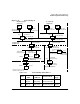
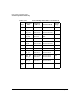

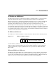
Table Of Contents
- About This Document
- 1 New for the HP-UX 11i v3 Release
- 2 Installing HP-UX LAN
- 3 Configuring HP-UX LAN Using SAM
- 4 Manually Installing and Configuring HP-UX LAN
- 5 Troubleshooting HP-UX LAN
- Troubleshooting Overview
- Troubleshooting Q & A
- LAN Interface Card Statistics
- 100Base-T Checklist
- Diagnostic Flowcharts
- Flowchart 1: Configuration Test
- Flowchart 2: Configuration Test continued
- Flowchart 3: Configuration Test continued
- Flowchart 4: Network Level Loopback Test
- Flowchart 5: Network Level Loopback Test continued
- Flowchart 6: Transport Level Loopback Test (using Internet Services)
- Flowchart 7: Link Level Loopback Test
- Flowchart 8: LAN Connections Test
- Flowchart 9: Gateway Remote Loopback Test
- Flowchart 10: Gateway Remote Loopback Test continued
- Flowchart 11: Subnet Test
- 6 LAN Resources
- 7 Network Addressing
- Overview of Network Addressing Schemes
- Networking Terminology
- Network Addresses and Node Names
- Internet Addresses
- Subnet Addresses
- Configuring Gateways on Fixed-Length Subnets
- Variable-Length Subnet Addressing
- Configuring Gateways on Variable-Length Subnets
- Configuring Gateways on Supernets
- IP Multicast Addresses
- Virtual IP (VIP) Addresses
- CIDR - Classless Inter-Domain Routing
- 8 LAN Device and Interface Terminology

DRAFT COPY Network Addressing
IP Multicast Addresses
Chapter 7 133
IP Multicast Addresses
IP multicasting provides a mechanism for sending a single datagram to a group of systems.
Generally, only systems that have joined the multicast group process the datagrams.
Multicast datagrams are transmitted and delivered with the same “best effort” reliability as
regular unicast IP datagrams. The datagrams are not guaranteed to arrive intact at all
members of the destination group or in the same order as the datagrams were sent.
Membership in a multicast group is dynamic. Systems can join or leave groups at any time
based upon the applications’ behavior. A system remains a member of a multicast group until
the last socket that joined the group is closed or drops membership in the group. A system can
be a member of more than one group at a time. A system that has multiple interfaces might be
a member of the same group on each interface.
IP Multicast Addresses
At the IP layer, a multicast address is a Class D Internet address with the following format:
Figure 7-15 Multicast Address Format
User IP multicast addresses can be in the range 224.0.1.0 through 239.255.255.255. The
addresses 224.0.0.0 through 224.0.0.255 are reserved. The addresses of other well-known
permanent multicast groups are published in the “Assigned Numbers” RFC (RFC-1060,
March 1990).
Ethernet Multicast Addresses
The Ethernet data-link address, also called the link level or station address, is derived from
the IP multicast address. The lower 23 bits of the IP multicast address are placed into the
lower 23 bits of the Ethernet multicast address 01-00-5E-00-00-00 (hex). Ethernet multicast
addresses can be in the range 01-00-5E-00-00-01 through 01-00-5E-7F-FF-FF.
1110
031 30 29 28 27
MULTICAST GROUP ADDRESS