
HP-UX LAN Administrator's Guide (Feburary 2007)
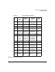
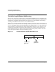
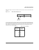
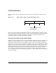
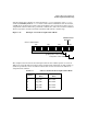
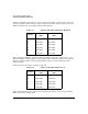
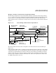
Table Of Contents
- About This Document
- 1 New for the HP-UX 11i v3 Release
- 2 Installing HP-UX LAN
- 3 Configuring HP-UX LAN Using SAM
- 4 Manually Installing and Configuring HP-UX LAN
- 5 Troubleshooting HP-UX LAN
- Troubleshooting Overview
- Troubleshooting Q & A
- LAN Interface Card Statistics
- 100Base-T Checklist
- Diagnostic Flowcharts
- Flowchart 1: Configuration Test
- Flowchart 2: Configuration Test continued
- Flowchart 3: Configuration Test continued
- Flowchart 4: Network Level Loopback Test
- Flowchart 5: Network Level Loopback Test continued
- Flowchart 6: Transport Level Loopback Test (using Internet Services)
- Flowchart 7: Link Level Loopback Test
- Flowchart 8: LAN Connections Test
- Flowchart 9: Gateway Remote Loopback Test
- Flowchart 10: Gateway Remote Loopback Test continued
- Flowchart 11: Subnet Test
- 6 LAN Resources
- 7 Network Addressing
- Overview of Network Addressing Schemes
- Networking Terminology
- Network Addresses and Node Names
- Internet Addresses
- Subnet Addresses
- Configuring Gateways on Fixed-Length Subnets
- Variable-Length Subnet Addressing
- Configuring Gateways on Variable-Length Subnets
- Configuring Gateways on Supernets
- IP Multicast Addresses
- Virtual IP (VIP) Addresses
- CIDR - Classless Inter-Domain Routing
- 8 LAN Device and Interface Terminology
Network AddressingDRAFT COPY
Variable-Length Subnet Addressing
Chapter 7120
This will allow for more growth bits between the subnet field and the host fields as shown
below.
Figure 7-11 Mirror Image Subnet and Host Field Allocation
In this case, both the host field and subnet field have considerably more growing space than
before, although the combined growing space is the same. As it is difficult to predict how many
hosts might end up in a subnet, or how many subnets there might eventually be, this
arrangement allows for maximum flexibility in growth.
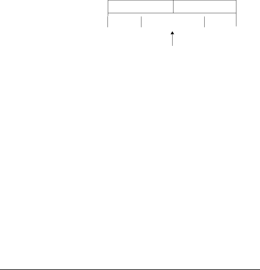
Assigning Variable-Length Subnet Masks
In Figure 7-11, the boundary between the host and subnet fields is shown in the middle of the
growth area. The boundary, however, could exist anywhere within the growth area. The
subnet mask determines where the boundary is located. “Ones” in the subnet mask indicate
subnet bits, and “zeros” indicate host bits. To minimize the amount of rework after the initial
planning of your network, you should choose a subnet mask for a given subnet based on the
projected growth of that subnet. As shown in Figure 7-12, the subnet is projected to have a
maximum size of 14 hosts. Therefore, the subnet mask should be 255.255.255.240. There are
two remaining growth bits for this subnet. If the subnet grows beyond 14 hosts, you may
choose to change one of the two remaining growth bits to a host bit. The new subnet mask will
be 255.255.255.224.
0s
1s & 0s
1s & 0s
subnet field host field
Both hosts and subnets
can grow here.