
HP-UX LAN Administrator's Guide (Feburary 2007)
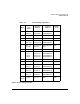
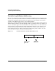
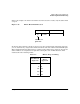
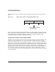
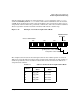
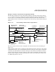
Table Of Contents
- About This Document
- 1 New for the HP-UX 11i v3 Release
- 2 Installing HP-UX LAN
- 3 Configuring HP-UX LAN Using SAM
- 4 Manually Installing and Configuring HP-UX LAN
- 5 Troubleshooting HP-UX LAN
- Troubleshooting Overview
- Troubleshooting Q & A
- LAN Interface Card Statistics
- 100Base-T Checklist
- Diagnostic Flowcharts
- Flowchart 1: Configuration Test
- Flowchart 2: Configuration Test continued
- Flowchart 3: Configuration Test continued
- Flowchart 4: Network Level Loopback Test
- Flowchart 5: Network Level Loopback Test continued
- Flowchart 6: Transport Level Loopback Test (using Internet Services)
- Flowchart 7: Link Level Loopback Test
- Flowchart 8: LAN Connections Test
- Flowchart 9: Gateway Remote Loopback Test
- Flowchart 10: Gateway Remote Loopback Test continued
- Flowchart 11: Subnet Test
- 6 LAN Resources
- 7 Network Addressing
- Overview of Network Addressing Schemes
- Networking Terminology
- Network Addresses and Node Names
- Internet Addresses
- Subnet Addresses
- Configuring Gateways on Fixed-Length Subnets
- Variable-Length Subnet Addressing
- Configuring Gateways on Variable-Length Subnets
- Configuring Gateways on Supernets
- IP Multicast Addresses
- Virtual IP (VIP) Addresses
- CIDR - Classless Inter-Domain Routing
- 8 LAN Device and Interface Terminology
Network AddressingDRAFT COPY
Variable-Length Subnet Addressing
Chapter 7118
Variable-Length Subnet Addressing
For the most efficient use of address space and maximum flexibility in increasing/decreasing
the size of your subnets, Hewlett-Packard recommends variable-length subnet addressing. To
maximize the possibilities offered with this new approach, you should utilize mirror image
counting, as described in this section, to select subnet numbers.
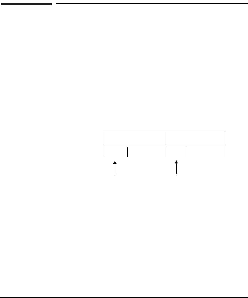
In the past, a network administrator typically assigned values to the subnet number and host
address fields in numerical order. For example, within a given subnet, hosts were numbers 1,
2, 3, etc. and within a given network, the subnets were numbered 1, 2, 3, etc. The result was
that some bits on the right side of the subnet field and host field were “ones and zeros” and
some bits on the left side of the subnet and host fields were “all zeros” for all subnets and
hosts. As shown below, the “all zeros” bits represented room for growth, and the “ones and
zeros” bits represented bits already consumed by growth.
Figure 7-9 Traditional Subnet and Host Field Allocation
0s
1s & 0s
0s 1s & 0s
subnet field host field
subnets can
grow here
hosts can
grow here