HP-UX LAN Administrator’s Guide HP-UX 11i v3 Manufacturing Part Number : 5991-7412 E0207 United States © Copyright 2007 Hewlett-Packard Development Company L.P. All rights reserved.
Legal Notices The information in this document is subject to change without notice. Hewlett-Packard makes no warranty of any kind with regard to this manual, including, but not limited to, the implied warranties of merchantability and fitness for a particular purpose. Hewlett-Packard shall not be held liable for errors contained herein or direct, indirect, special, incidental or consequential damages in connection with the furnishing, performance, or use of this material.
Contents About This Document 1. New for the HP-UX 11i v3 Release Deprecated System Administration Manager (SAM) . . . . . . . . . . . . . . . . . . . . . . . . . . 14 Deprecated LAN Commands . . . . . . . . . . . . . . . . . . . . . . . . . . . . . . . . . . . . . . . . . . . . . . 15 New nwmgr Command . . . . . . . . . . . . . . . . . . . . . . . . . . . . . . . . . . . . . . . . . . . . . . . . . . 16 2. Installing HP-UX LAN Overview . . . . . . . . . . . . . . . . . . . . . . . . . . . . . . . . . . . .
Contents LAN Interface Card Statistics. . . . . . . . . . . . . . . . . . . . . . . . . . . . . . . . . . . . . . . . . . . . . RFC 1213 MIB II STATISTICS . . . . . . . . . . . . . . . . . . . . . . . . . . . . . . . . . . . . . . . . . . RFC 1284 Ethernet-Like Interface Statistics . . . . . . . . . . . . . . . . . . . . . . . . . . . . . . . 100Base-T Checklist . . . . . . . . . . . . . . . . . . . . . . . . . . . . . . . . . . . . . . . . . . . . . . . . . . . . Diagnostic Flowcharts . . . . . . . . . . .
Contents Selecting a Subnet Addressing Scheme. . . . . . . . . . . . . . . . . . . . . . . . . . . . . . . . . . . Fixed-Length Subnet Addressing . . . . . . . . . . . . . . . . . . . . . . . . . . . . . . . . . . . . . . . Configuring Gateways on Fixed-Length Subnets . . . . . . . . . . . . . . . . . . . . . . . . . . . . Explicit Routing . . . . . . . . . . . . . . . . . . . . . . . . . . . . . . . . . . . . . . . . . . . . . . . . . . . . . Dynamic Routing . . . . . . . . . . . . . . . . . . . . . . . .
Contents vi
About This Document This document describes how to install, configure, and troubleshoot HP-UX 11i v3 LAN transport software. The document printing date and part number indicate the document’s current edition. The printing date will change when a new edition is printed. Minor changes may be made at reprint without changing the printing date. The document part number will change when extensive changes are made. Document updates may be issued between editions to correct errors or document product changes.
Publishing History Table 1 Publishing History Details Document Manufacturing Part Number Operating Systems Supported Publication Date 5991-7412 11i v3 Feburary 2007 B2355-90796 11i v2 July 2003 B2355-90748 11i v1.6, 11i v1, 11.0, 10.x March 2002 What’s in This Document This manual provides information for installing and administering the HP-UX LAN product. The HP-UX LAN product allows HP computers to connect to an IEEE 802.3 or Ethernet Local Area Network.
Chapter 4 Troubleshooting HP-UX LAN provides flowcharts to help diagnose HP-UX LAN software and hardware problems. This chapter also describes LAN card status values and statistics returned by lanadmin. Chapter 5 LAN Resources provides references to other useful tools for installing, configuring, and maintaining HP-UX LAN software. Chapter 6 Network Addressing defines networking terms and explains network interface names, network addresses, names and subnets.
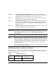
Table 2 HP-UX 11i Releases (Continued) Release Identifier Release Name Supported Processor Architecture B.11.23 HP-UX 11i v2 Intel® Itanium® B.11.22 HP-UX 11i v1.6 Intel® Itanium® B.11.20 HP-UX 11i v1.5 Intel® Itanium® B.11.11 HP-UX 11i v1 PA-RISC Related Documents HP Documentation Additional information about HP-UX LAN can be found within docs.hp.com in the networking and communications collection under HP-UX LAN at: http://www.docs.hp.com/hpux/netcom/index.
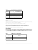
Table 3 LAN Protocols and Standards (Continued) For Information on: Read: Requirements for IP Version 4 Routers RFC 1812 Variable Length Subnet Table RFC 1878 Protocols: Address Resolution Protocol (ARP) RFC 826 Domain Requirements RFC 920 Domain Name Server RFC 1034, 1035, 1535 Internet Control Message Protocol (ICMP) RFC 792 Internet Protocol (IP) MIL-STD 1777; RFC 791 Standard for the Format of ARPA Internet Text Messages RFC 822 Transmission Control Protocol (TCP) MIL-STD 1788; RFC
HP Welcomes Your Comments HP welcomes your comments concerning this document. We are truly committed to providing documentation that meets your needs. Please send comments to: netinfo_feedback@cup.hp.com Please include document title, manufacturing part number, and any comment, error found, or suggestion for improvement you have concerning this document. Also, please tell us what you like, so we can incorporate it into other documents.
DRAFT COPY New for the HP-UX 11i v3 Release 1 New for the HP-UX 11i v3 Release The HP-UX 11i v3 release has the following changes: • “Deprecated System Administration Manager (SAM)” on page 14 • “Deprecated LAN Commands” on page 15 • “New nwmgr Command” on page 16 Chapter 1 13
New for the HP-UX 11i v3 ReleaseDRAFT COPY Deprecated System Administration Manager (SAM) Deprecated System Administration Manager (SAM) The System Administration Manager (SAM) was an HP-UX System Administration tool that provided various tools for performing system administration tasks. In the 11i v3 release of HP-UX, System Administration Manager (SAM) is deprecated. HP System Management Homepage (HP SMH), an enhanced version of SAM, is introduced for managing HP-UX.
DRAFT COPY New for the HP-UX 11i v3 Release Deprecated LAN Commands Deprecated LAN Commands The LAN administration and display commands, namely, lanadmin, lanscan, and linkloop are deprecated and will be removed in a future release. HP recommends the use of the replacement command, nwmgr, for performing these LAN functions. For more information about the nwmgr command, see “New nwmgr Command” on page 16 and nwmgr (1M).
New for the HP-UX 11i v3 ReleaseDRAFT COPY New nwmgr Command New nwmgr Command A new command, nwmgr, is introduced on HP-UX 11i v3 release. The nwmgr command is a unified management command line tool. It enables management of Local Area Network (LAN) based network interfaces and supports the functionalities of legacy LAN commands (lanadmin, lanscan, and linkloop). The nwmgr command line interface usage format is different from the legacy LAN command line interface usage format.
2 Installing HP-UX LAN This chapter describes the manual procedures to load HP-UX LAN software and to install LAN hardware onto your system.
Installing HP-UX LANDRAFT COPY Overview Overview This chapter contains the following sections: • Step 1: Checking LAN Installation Prerequisites • Step 2: Loading LAN Software • Step 3: Installing LAN Hardware IMPORTANT If you have a system with HP-UX LAN pre-installed on it, you may skip this chapter and go directly to chapter 2. Execute the command lanscan or nwmgr to determine if the HP-UX LAN software and hardware have been pre-installed.
DRAFT COPY Installing HP-UX LAN Checking LAN Installation Prerequisites Checking LAN Installation Prerequisites Prior to loading the HP-UX LAN product onto your system, check that you have met the following hardware and software prerequisites: • Check that /usr/bin, /usr/sbin, and /sbin are in your PATH using the command: echo $PATH • The operating system should have been upgraded to HP-UX 11i v3 software.
Installing HP-UX LANDRAFT COPY Loading LAN Software Loading LAN Software Follow the steps below to load the HP-UX LAN software using the HP-UX swinstall program. 1. Log in as root. 2. Check that /usr/bin, /usr/sbin, and /sbin are in your PATH. 3. Insert the software media into the appropriate drive. 4. Run the swinstall program using the command: swinstall This opens the Software Selection Window and Specify Source Window. 5.
DRAFT COPY Installing HP-UX LAN Installing LAN Hardware Installing LAN Hardware Follow the steps below to prepare the system for installation of your network interface hardware. 1. At the HP-UX prompt, execute the command: shutdown -h Wait for the system to respond with a message indicating that the system has been halted. 2. Observe antistatic precautions by following the guidelines as described in the installation instructions in the hardware manual or the Antistatic Precautions Note. 3.
Installing HP-UX LANDRAFT COPY Installing LAN Hardware 6 Chapter 2
3 Configuring HP-UX LAN Using SAM NOTE Chapter 3 In the 11i v3 release of HP-UX, System Administration Manager (SAM) is deprecated.
Configuring HP-UX LAN Using SAMDRAFT COPY version of SAM, is introduced for managing HP-UX. However, you can also use the sam command. The sam command behaves the same as smh command except that the deprecation message is displayed in the beginning. This chapter describes how to configure LAN using SAM, the System Administration Manager.
DRAFT COPY Configuring HP-UX LAN Using SAM Overview of Configuration Using SAM Overview of Configuration Using SAM Once you have installed hardware and software, you can use SAM to automatically configure networking. SAM stands for System Administration Manager, a menu-driven utility for system administration tasks, including configuration of networking software. SAM has two user interfaces, an X-Windows system interface and a text terminal interface.
Configuring HP-UX LAN Using SAMDRAFT COPY Configuring the Network Interface Card Configuring the Network Interface Card Make sure the LAN card and driver are installed in the system before you use SAM to configure the software. NOTE Log in as root and do the following: 1. At the HP-UX prompt, type: sam 2. Select the Networking and Communications item of the SAM main window. 3. Select the Network Interface Cards item of the Networking and Communications window. 4.
DRAFT COPY Configuring HP-UX LAN Using SAM Configuring the Network Interface Card c. Enter the Internet address for your LAN card. Upon exiting the Internet Address field, SAM checks to make sure that the IP address you entered is correctly formatted and is not currently in use. d. Specify whether your LAN card will be on a subnetwork or supernet. The Subnet Mask field can contain a fixed-length subnet mask, a variable-length subnet mask, or a supernet mask.
Configuring HP-UX LAN Using SAMDRAFT COPY Configuring the Network Interface Card crw-rw-rw- 1 bin bin 72 0x000077 Dec 4 11:14 /dev/dlpi The major number, shown in the fifth column, must be 72 (decimal) and the minor number, shown in the sixth column, must be 77 (hexadecimal). If the major numbers or minor numbers are not correct, delete the device file and recreate it with the correct numbers using the mknod command.
DRAFT COPY Configuring HP-UX LAN Using SAM Configuring Network Connectivity Configuring Network Connectivity Your system may not be able to communicate with other systems (for example, PCs, workstations, servers, etc.) until you configure system-to-system connections. You can use SAM to do this automatically by completing the following steps: 1. At the HP-UX prompt, type: sam 2. Double-click on the Networking and Communications item of the SAM main window. 3. Double-click on Hosts.
Configuring HP-UX LAN Using SAMDRAFT COPY Configuring Network Connectivity NOTE You can modify or remove remote systems and modify default gateways by highlighting the Remote System Name from the object list and choosing Modify, Remove, or Modify Default Gateway from the “Actions” menu. 6. Choose Exit from the “File” menu. 7. Then Exit SAM from the “File” menu again. 8. Verify remote system configuration. a.
DRAFT COPY Configuring HP-UX LAN Using SAM Verifying the Installation Verifying the Installation Once your HP-UX LAN software is installed, fully configured and running, you should execute the following commands to verify LAN hardware and software installation. See the man pages for complete descriptions of the commands listed below. 1. Check the state of all LAN hardware. To do so execute the lanscan or nwmgr command and verify that the Hardware State is UP. See lanscan(1M) or nwmgr(1M) for details. 2.
Configuring HP-UX LAN Using SAMDRAFT COPY Reconfiguring IP Addresses Reconfiguring IP Addresses If you have rearranged any network interface cards in the system you may need to reconfigure the IP addresses. Follow the steps below: 1. At the HP-UX prompt, type: sam 2. At the main menu select the Networking and Communications item. 3. Select the Network Interface Cards item. 4.
4 Manually Installing and Configuring HP-UX LAN This chapter provides information on manually configuring HP-UX LAN software.
Manually Installing and Configuring HP-UX LANDRAFT COPY • Creating a New Kernel • Verifying LAN Device Files • Editing Driver Configuration Files • Editing LAN Configuration Files • Creating the /etc/hosts File • Activating Optional Network Features 18 Chapter 4
DRAFT COPY Manually Installing and Configuring HP-UX LAN Creating a New Kernel Creating a New Kernel Before attempting this procedure, familiarize yourself with the system reconfiguration information in the mk_kernel(1M) man page and HP-UX system literature. Refer to the System Administration manual for your system for complete instructions on how to create a kernel.
Manually Installing and Configuring HP-UX LANDRAFT COPY Creating a New Kernel b. Depending on which filesets you have loaded, you may also need to add the following keywords to the system file: Table 4-1 Keywords Keyword Comments hpstreams required for streams dlpi required uipc required for TCP/IP inet required for TCP/IP nms required for TCP/IP nfs_core nfs_client nfs_server netdiag1 tun required for PPP 5. Make a copy of the existing kernel (default name vmunix). 6.
DRAFT COPY Manually Installing and Configuring HP-UX LAN Creating a New Kernel 9. Proceed to the next section “Verifying LAN Device Files,” in this chapter to continue configuring HP-UX LAN manually. To configure your system with the SAM utility, proceed to Chapter 3, “Configuring HP-UX LAN Using SAM.
Manually Installing and Configuring HP-UX LANDRAFT COPY Verifying LAN Device Files Verifying LAN Device Files All IP access to LAN devices is done through the files /dev/lan and /dev/snap, which are symbolically linked to the Data Link Provider Interface (DLPI) device file /dev/dlpi. The /dev/dlpi file is automatically created at installation time.
DRAFT COPY Manually Installing and Configuring HP-UX LAN Editing Driver Configuration Files Editing Driver Configuration Files If needed, edit appropriate configuration files. Refer to your specific Ethernet LAN documentation, as appropriate for your configuration, for complete information. Below are some examples of software driver names, configuration files, and init scripts for Fast Ethernet and Gigabit Ethernet cards/adapters.
Manually Installing and Configuring HP-UX LANDRAFT COPY Editing LAN Configuration Files Editing LAN Configuration Files To configure and initialize LAN manually, you must edit the /etc/rc.config.d/netconf file and execute the HP-UX LAN initialization script. To do so, you must be logged on as root. The script reads the information in the edited netconf file when the system reboots and performs the following: • Configures the network interface with an IP address and optional subnet mask.
DRAFT COPY Manually Installing and Configuring HP-UX LAN Editing LAN Configuration Files CAUTION Each HP LAN card has a preset station address, for example 080009xxxxxx. This address must be modified with caution. Modifying the station address of an active card will probably destroy existing connections and traffic resulting in data loss. The station address configuration parameters have an index value, [x], that groups the station address parameters together.
Manually Installing and Configuring HP-UX LANDRAFT COPY Editing LAN Configuration Files BROADCAST_ADDRESS[0]=”” INTERFACE_STATE[0]=”” DHCP_ENABLE[0]=”0” If you have more than one interface to configure, you must have a complete set of internet configuration parameters for each interface. The index value must be different for each additional interface. The network interface name in lanscan corresponds to the INTERFACE_NAME[x] in the internet configuration parameters.
DRAFT COPY Manually Installing and Configuring HP-UX LAN Editing LAN Configuration Files Option 1: Reboot your system. HP recommends that you reboot your system to activate any changes you made in your netconf file. A reboot is the cleanest method for executing the network script because the reboot handles any other network initialization dependencies. Option 2: Execute the ifconfig and route commands at the HP-UX prompt. HP recognizes that system reboots are disruptive to end users.
Manually Installing and Configuring HP-UX LANDRAFT COPY Creating the /etc/hosts File Creating the /etc/hosts File You must edit the /etc/hosts file to add an IP address and hostname for the LAN card that you are installing. NOTE If you are using a naming service (DNS or NIS), you will need to modify the /etc/hosts file to add the IP address and host name to the appropriate databases on the name server system.
DRAFT COPY Manually Installing and Configuring HP-UX LAN Creating the /etc/hosts File host3 /etc/rc.config.d/netconf file: HOSTNAME=host3 /etc/hosts file: 192.6.1.1 host3 host3.site2.region4 uname -S host3 hostname host3 NOTE When you first install a system, the netconf HOSTNAME entry, the /etc/hosts entry, the hostname, and uname -S are set for you automatically. /etc/hosts Each node has a one line entry in the /etc/hosts file.
Manually Installing and Configuring HP-UX LANDRAFT COPY Creating the /etc/hosts File • Comments are allowed and designated by a pound sign (#) preceding the comment text. • Trailing blank and tab characters are allowed. • Blank line entries are allowed. • Only one host entry per line is allowed. /etc/hosts Permissions HP recommends that the /etc/hosts file be owned by user root and have 0x444 (-r--r--r--) access permission.
DRAFT COPY Manually Installing and Configuring HP-UX LAN Activating Optional Network Features Activating Optional Network Features To activate special network features, you may also want to configure /etc/services, /etc/networks, and /etc/protocols. Each of these steps is optional. NOTE If you are using NIS, modifications to the /etc/services, /etc/networks and /etc/protocols files should only be made on the NIS Master Server.
Manually Installing and Configuring HP-UX LANDRAFT COPY Activating Optional Network Features alias Common name or names for the service. An alias is a substitute for service_name. Alias names are optional. /etc/services Format • Lines cannot start with a blank or tab character. • Fields can have any number of blanks or tab characters separating them. • Comments are allowed and designated by a pound sign (#) character preceding the comment text. • Trailing blank and tab characters are allowed.
DRAFT COPY Manually Installing and Configuring HP-UX LAN Activating Optional Network Features If you copy an /etc/networks file from another host, you may need to update the file by adding unofficial aliases or unknown networks, including your own network. /etc/networks Each network has a one line entry in the /etc/networks file. Each entry in /etc/networks file takes the following form: Syntax network_name network_address [alias]... Parameters network_name Name of the internet network.
Manually Installing and Configuring HP-UX LANDRAFT COPY Activating Optional Network Features /etc/networks Example The following /etc/networks entry contains a network name, network address, and an alias name for the network neta. neta 192.6.1 testlan Modifying the /etc/protocols File The /etc/protocols file associates port numbers with mnemonic names and alias names. The /etc/protocols file contains the names and protocol numbers of all protocols known to your local host.
DRAFT COPY Manually Installing and Configuring HP-UX LAN Activating Optional Network Features • Blank line entries are allowed. • Only one entry per line is allowed. /etc/protocols Permissions The /etc/protocols file should be owned by user bin, group bin, and it should have 0x444 (-r--r--r--) access permission. Refer to the /etc/protocols file for examples of actual format and contents. For more information on /etc/protocols, refer to the protocols(4) man page in the HP-UX Reference Pages.
Manually Installing and Configuring HP-UX LANDRAFT COPY Activating Optional Network Features 36 Chapter 4
5 Troubleshooting HP-UX LAN This chapter provides guidelines for troubleshooting H-UX LAN.
Troubleshooting HP-UX LANDRAFT COPY • Troubleshooting Q and A • LAN Interface Card Statistics • 100Base-T Checklist • Diagnostic Flowcharts 38 Chapter 5
DRAFT COPY Troubleshooting HP-UX LAN Troubleshooting Overview Troubleshooting Overview Troubleshooting LAN problems can be difficult because a variety of hardware and software components may be involved and because the problem impacting your system may originate in another part of the network. The “Troubleshooting Q and A” section in this chapter provide quick fix solutions to common network problems by providing answers to the most frequently asked troubleshooting questions.
Troubleshooting HP-UX LANDRAFT COPY Troubleshooting Q & A Troubleshooting Q & A New system disrupts LAN: I tried to attach a new system to our site LAN. To make the installation process faster, I copied over an /etc/rc.config.d/netconf file from another system on the site LAN and used it on the new system. When I booted up the system, the site LAN went down. Answer: You probably didn't assign a new IP address and host name prior to rebooting the system.
DRAFT COPY Troubleshooting HP-UX LAN Troubleshooting Q & A Answer: Addresses with the format 127.n.n.n are reserved as loopback addresses. Select another IP address. You can obtain Class C addresses that are unique within the ARPANET by contacting Government Systems, Inc. Related Documentation: Refer to “Assigning an Internet Address” in Chapter 6.
Troubleshooting HP-UX LANDRAFT COPY Troubleshooting Q & A The file, filename.TRC0 is the most recent trace file. If this file does not contain the trace information you are looking for, check the filename.TRC1 file. To format your LAN trace using a filter file, execute: netfmt -c filterfile -N -f filename.TRC0 > fmt0 nettl appends TRC0 or TRC1 to the name you give the raw trace file. Related Documentation: Refer to Chapter 5, “LAN Resources.
DRAFT COPY Troubleshooting HP-UX LAN Troubleshooting Q & A Answer: On IEEE802.3/Ethernet networks, a collision occurs when two or more stations try to transmit data simultaneously. A deferred transmission occurs if the network is busy when a station attempts to transmit data. The number of collisions and deferred transmissions on a node is directly related to the network load. As the network load increases, the number of collisions and deferred transmissions also increase.
Troubleshooting HP-UX LANDRAFT COPY Troubleshooting Q & A Can’t communicate outside local supernet: I recently tried to set up a supernet on my LAN. The systems in the supernet can communicate with one another, but they cannot communicate with systems outside the supernet. Answer: Check the routing table on your system and the node you want to communicate with.
DRAFT COPY Troubleshooting HP-UX LAN LAN Interface Card Statistics LAN Interface Card Statistics This section contains descriptions of the RFC 1213 MIB II statistics fields for LAN interface cards which are displayed on the screen with the display command in lanadmin LAN Interface Test Mode. A description of each field follows the display. LAN INTERFACE STATUS DISPLAY Mon, May 19,2003 11:16:22 Network Management ID = 1 Description = lan0 HP PCI Core I/O 1000Base-T Release B.11.23.00.
Troubleshooting HP-UX LANDRAFT COPY LAN Interface Card Statistics RFC 1213 MIB II STATISTICS Description A textual string containing information about the interface. This string includes the name of the manufacturer, the product name and the version of the hardware interface. Type (value) The type of interface, distinguished according to the physical/link protocol(s) immediately below the network layer in the protocol stack.
DRAFT COPY Troubleshooting HP-UX LAN LAN Interface Card Statistics Table 5-1 Type(value)/Comments (Continued) basicISDN(20) primaryISDN(21) Proprietary serial proPointToPointSerial( 22) ppp(23) softwareLoopback(24) eon(25) CLNP over IP [11] ethernet-3Mbit(26) nsip(27) XNS over IP slip(28) generic SLIP ulta(29) ULTRA technologies ds3(30) T-3 sip(31) SMDS frame-relay(32) MTU Size The size of the largest datagram which can be sent/received on the interface specified in octets.
Troubleshooting HP-UX LANDRAFT COPY LAN Interface Card Statistics Table 5-2 testing(3) Administration Status (Continued) In test mode Operation Status The current operational state of the interface. It will have one of the following values. Table 5-3 Operation Status up(1) Ready to pass packets down(2) Not operative testing(3) In test mode Last Change The value of SysUpTime at the time the interface entered its current operational state.
DRAFT COPY Troubleshooting HP-UX LAN LAN Interface Card Statistics Outbound Non-Unicast Packets The total number of packets that higher-level protocols requested be transmitted to a non-unicast (a subnetwork-broadcast or subnetwork-multicast) address, including those that were discarded or not sent. Outbound Discards The number of outbound packets that were discarded even though no errors had been detected to prevent their being transmitted.
Troubleshooting HP-UX LANDRAFT COPY LAN Interface Card Statistics Internal MAC Receive Errors A count of frames for which reception on a particular interface fails due to an internal MAC sublayer receive error 50 Chapter 5
DRAFT COPY Troubleshooting HP-UX LAN 100Base-T Checklist 100Base-T Checklist In case of trouble with 100Base-T LAN links, you can use the following procedures to troubleshoot your network problems: • Verify Cabling: make sure the connection is secured, UTP Category 5 is used, the card is well inserted. Also, assure the cable length is not within 35 - 41 meters. Check the cable running from the HP adapter to the Switch, and the Switch port, in case either is defective.
Troubleshooting HP-UX LANDRAFT COPY 100Base-T Checklist Or use the lanscan or nwmgr command to get the name of the Net Interface Name or ppa number or nmid number. Once you have the ppa number, for example lan17, you can issue these following commands one at a time: lanadmin lan ppa 17 display The Operation Status should be DOWN. Or, use as follows, to get the entire list of interfaces on your system.
DRAFT COPY Troubleshooting HP-UX LAN 100Base-T Checklist - Patch(es) for lanadmin - current lanadmin provides the lanadmin -x -X functionality. - Patch(es) for SAM - all systems need an updated SAM patch because SAM can “step on” the 100Base-T configuration file Duplex mode.
Troubleshooting HP-UX LANDRAFT COPY Diagnostic Flowcharts Diagnostic Flowcharts Below is a summary of the types of network tests in the diagnostic flowcharts. To diagnose your problem, first check the connections and configuration on your system (Flowcharts 1 through 5). If this does not solve your problem, use flowcharts 6 through 11 to test/verify connectivity with a remote system.
DRAFT COPY Troubleshooting HP-UX LAN Diagnostic Flowcharts Subnet Test: Verifies the correct use of subnets. Figure 5-1 Loopback Tests OSI Layer telnet showmount (NFS) 6&7 5 4 Virtual Terminal NFS Services Internet Services BSD Sockets XTI TCP UDP ping 3 2 IP ICMP ARP LAN Driver DLPI lanadmin linkloop or nwmgr Network Interface Card 1 MAU The loopback tests shown in Figure 5-1 are used to isolate a network communication problem that may be software- or hardware-related.
Troubleshooting HP-UX LANDRAFT COPY Diagnostic Flowcharts The netstat utility reports network and protocol statistics regarding traffic and the local LAN interface. As shown in Figure 5-2, there are many options to netstat. The options that are most useful are those which display information that is not available through other commands such as ping and lanadmin, for example, -a and -r options. You can also use the lanadmin or nwmgr command to obtain LAN driver statistics.
DRAFT COPY Troubleshooting HP-UX LAN Diagnostic Flowcharts Flowchart 1: Configuration Test Figure 5-3 Flowchart 1 1 A Execute: lanscan or nwmgr C B All interfaces configured ? no Execute: ioscan yes 2 D bind errors? no F E Correct driver in system file? no Add correct driver and regen yes Call HP Chapter 5 1 57
Troubleshooting HP-UX LANDRAFT COPY Diagnostic Flowcharts Flowchart 1 Procedures A. Execute: lanscan or nwmgr. Execute lanscan or nwmgr to display information about LAN cards that are successfully bound to the system. For example, to check the cards on /stand/vmunix, enter: lanscan Or, nwmgr B. All interfaces configured? lanscan or nwmgr is successful if the output shows information about every card in the hardware backplane. C. Execute ioscan. Execute the ioscan command to check for bind errors. D.
DRAFT COPY Troubleshooting HP-UX LAN Diagnostic Flowcharts Flowchart 2: Configuration Test continued Figure 5-4 Flowchart 2 2 A Execute ifconfig B C ifconfig successful ? E no D no Any error message returned? yes Correct ifconfig flag settings 2 yes 3 Execute: netstat -in G F Interface name correct? no Correct encapsulation using ifconfig yes I H Suspect LAN card I/O problem ? yes Execute lanadmin or nwmgr J Problem resolved ? Chapter 5 Call HP yes no 4 no Stop E
Troubleshooting HP-UX LANDRAFT COPY Diagnostic Flowcharts Flowchart 2 Procedures A. Execute: ifconfig . Execute ifconfig on the interface you want to test. For example, to check LAN interface lan0, enter: ifconfig lan0 B. ifconfig successful? ifconfig is successful if the output shows the correct Internet address and the flags, typically: UP,BROADCAST,RUNNING. C. Any error message returned? If ifconfig is not successful, and an error message appears, go to Flowchart 3.
DRAFT COPY Troubleshooting HP-UX LAN Diagnostic Flowcharts nwmgr -g --st -c lanPPA. If the values of the Inbound Errors and Outbound Errors increase substantially during a file transfer attempt, this can indicate transmission or reception problems. Refer to “LAN Interface Card Statistics” in this chapter for more information. J. Chapter 5 Problem resolved? If you have found and corrected the LAN card problem, stop. If not, call your HP representative for help.
Troubleshooting HP-UX LANDRAFT COPY Diagnostic Flowcharts Flowchart 3: Configuration Test continued Figure 5-5 Flowchart 3 3 A E C ifconfig not found No such interface Bad system call Restore ifconfig from media Execute: lanscan or nwmgr Reconfigure HP-UX kernel to include HP-UX LAN G 1 yes Execute: /sbin/init.d/net .
DRAFT COPY Troubleshooting HP-UX LAN Diagnostic Flowcharts Flowchart 3 Procedures A. ifconfig not found. The command has been relocated on the system, deleted, or /usr/sbin is not in your PATH. B. Restore /etc/ifconfig from media. You can restore ifconfig from the last good backup tape or your install/update tape. Go to Flowchart 2. C. Bad system call. Networking is not configured into the HP-UX kernel. D. Reconfigure HP-UX kernel to include HP-UX LAN software.
Troubleshooting HP-UX LANDRAFT COPY Diagnostic Flowcharts N. 64 Any other error message. If you received an error message not listed on this flowchart, interpret the message and take the appropriate action. If you need assistance, call your HP representative. Be prepared to discuss the problem as described in “Contacting Your HP Representative” in Chapter 5, “LAN Resources.
DRAFT COPY Troubleshooting HP-UX LAN Diagnostic Flowcharts Flowchart 4: Network Level Loopback Test Figure 5-6 Flowchart 4 4 A Execute: ping to remote host B C ping successful? no Network unreachable ? yes Local LAN interface up ? no yes Stop D yes F no Call HP E yes Command hangs? Configure interface up 5 no G 4 H Unknown host? yes Correct BIND, NIS, or /etc/hosts configuration 4 no J I No route to host? yes Add route table entry 4 no Call HP Chapter 5 65
Troubleshooting HP-UX LANDRAFT COPY Diagnostic Flowcharts Flowchart 4 Procedures A. Execute: ping to remote host. Using ping, send a message to the remote host with which you are having problems connecting. For example, suppose the remote host is known as 192.6.20.2. Enter: ping 192.6.20.2 NOTE B. HP recommends using the IP address, rather than the hostname, as part of the problem may be an error in the /etc/hosts file or connectivity with a name server.
DRAFT COPY Troubleshooting HP-UX LAN Diagnostic Flowcharts I. No route to host? (Error= Sendto: No route to host?) Use netstat -rn to check the routing table. If there is no route table entry for the host, go to J. Otherwise, call your HP representative for help. Be prepared to discuss the problem as described in “Contacting Your HP Representative” in Chapter 5, “LAN Resources”. J. Add route table entry. Using route, add a route table entry for that host.
Troubleshooting HP-UX LANDRAFT COPY Diagnostic Flowcharts Flowchart 5: Network Level Loopback Test continued Figure 5-7 Flowchart 5 5 A B Host entry in ARP cache ? C yes no Remote host up? E yes yes LAN card OK? no no Bring up remote host Call HP D Replace or reset LAN card 4 G F Entry complete? no Use arp to complete entry 4 yes H ping local host I ping successful? yes 4 68 no Call HP Note: This time ping from remote host to local host Chapter 5
DRAFT COPY Troubleshooting HP-UX LAN Diagnostic Flowcharts Flowchart 5 Procedures A. Host entry in ARP cache? Using arp, check that an entry exists for the remote host in your system's ARP cache. For example, suppose the remote host is known as 192.6.20.2. Enter: arp 192.6.20.2 B. Remote host up? If there is no ARP cache entry for the remote host, first check that the remote host is up. If not, the remote host has not broadcast an ARP message, and that likely is why there is no entry in the ARP cache.
Troubleshooting HP-UX LANDRAFT COPY Diagnostic Flowcharts Flowchart 6: Transport Level Loopback Test (using Internet Services) Figure 5-8 Flowchart 6 6 A Execute: telnet to remote host B yes Successful? C Stop no Execute: ftp to remote host D yes Successful? E G Check for network congestion Call HP 70 Call HP no TCP yes configured on local or remote host? F no Configure TCP 6 Chapter 5
DRAFT COPY Troubleshooting HP-UX LAN Diagnostic Flowcharts Flowchart 6 Procedures A. Execute: telnet to remote host. Try to establish a telnet connection to the remote host. B. Successful? If your telnet attempt was successful, stop. The connection is okay through the Transport Layer (OSI Layer 4). C. Execute: ftp to remote host. Unlike telnet, ftp does not go through a pseudo-terminal driver (pty) on your system. This step tests to see if the pty is why telnet failed. D.
Troubleshooting HP-UX LANDRAFT COPY Diagnostic Flowcharts Flowchart 7: Link Level Loopback Test Figure 5-9 Flowchart 7 7 A Execute: linkloop or nwmgr -- diag on local interface C B D yes yes Execute linkloop or nwmgr --diag to remote host Successful? Successful? Stop no 8 G F E Loopback FAILED: Address has bad format Loopback FAILED: Not an individual address I H Correct the link address parameter K 7 72 Check remote host connectivity to LAN Loopback FAILED Choose a different remote IE
DRAFT COPY Troubleshooting HP-UX LAN Diagnostic Flowcharts Flowchart 7 Procedures A. Execute: linkloop or nwmgr --diag on local interface. Execute the linkloop or nwmgr --diag command with the station address of the local interface. Execute lanscan or nwmgr to find the link level address (station address) on the remote host or obtain it from your network map. For more information, refer to the linkloop(1M) or nwmgr(1M) man page. B. successful? If not, your LAN card may not be operational.
Troubleshooting HP-UX LANDRAFT COPY Diagnostic Flowcharts Flowchart 8: LAN Connections Test Figure 5-10 Flowchart 8 8 B A Thick Coax ThinLAN Thick or thin cabling ? Check: AUI solidly connected to LAN card G Check: AUI solidly connected to MAU and LAN card No H A1 C Check: Backbone cable terminated at both ends RJ45 LED = ON ? Check: ThinLAN cable terminated at both ends I A2 RJ45: Card seated securedly D Check: BNC T-connectors secure E Check: ThinLAN cable grounded in only one place Che
DRAFT COPY Troubleshooting HP-UX LAN Diagnostic Flowcharts Flowchart 8 Procedures A. Thick or thin cabling? If your network cabling is the thicker coaxial cabling, continue in the direction marked “Thick Coax.” If your network cabling is the ThinLAN cabling, continue in the direction marked “ThinLAN.” A1. RJ45 Adapter? Verify LEDs. Network Activity and Link Status LED displays: Link Status LED is lit GREEN for a valid link. Network Activity LED is lit AMBER color for both 10 Mbps and 100Mbps.
Troubleshooting HP-UX LANDRAFT COPY Diagnostic Flowcharts K. 76 Check: Backbone cable grounded in only one place. Make sure the backbone cable is grounded in only one place.
DRAFT COPY Troubleshooting HP-UX LAN Diagnostic Flowcharts Flowchart 9: Gateway Remote Loopback Test Figure 5-11 Flowchart 9 9 A B Execute: ping from known good host through gateway to known good remote host ping successful ? yes Stop no C Execute: netstat -rn E D Add route entry on local system Direct route to remote or default route to gateway? no yes 10 F G Routing table on remote OK? no Correct routing table yes 10 Chapter 5 4 77
Troubleshooting HP-UX LANDRAFT COPY Diagnostic Flowcharts Flowchart 9 Procedures A. Execute: ping from known good host through gateway to known good host on remote network. This will test gateway connectivity to the remote network. For more information on ping, refer to chapter 6. B. ping successful? If the executing ping returned does not return successfully, the problem may exist in the routing table for the problem host. Go to C. C. Execute netstat -rn.
DRAFT COPY Troubleshooting HP-UX LAN Diagnostic Flowcharts Flowchart 10: Gateway Remote Loopback Test continued Figure 5-12 Flowchart 10 10 no A Examine gateway B D Other HP; other vendors C Refer to networking documentation HP-UX E Execute: ifconfig on gateway host F G Network interface up? no Configure interface up yes 1 Chapter 5 4 79
Troubleshooting HP-UX LANDRAFT COPY Diagnostic Flowcharts Flowchart 10 Procedures A. Examine gateway. If the gateway is an HP-UX Server, go to D. If it is not, go to B. B. Other HP; other vendors. Go to C. C. Refer to networking documentation. Refer to the documentation that came with the gateway for additional diagnostics. D. HP-UX. Go to E. E. Execute: ifconfig on gateway host. Execute ifconfig for all network interfaces on the gateway. NOTE F. Running is always displayed by ifconfig output.
DRAFT COPY Troubleshooting HP-UX LAN Diagnostic Flowcharts Flowchart 11: Subnet Test Figure 5-13 Flowchart 11 11 A I D Host portion all 0s or all 1s? no no Correct IP address Subnet mask set to what you expect? 11a yes yes B E Correct IP address J All hosts on subnet using same subnet mask? no Correct subnet mask 11a yes 11 F G K All hosts on network have subnet mask set? no Correct subnet mask yes Check route table on source, destination 11a H Stop Chapter 5 Correct route tab
Troubleshooting HP-UX LANDRAFT COPY Diagnostic Flowcharts Flowchart 11 Procedures A. Host Portion all 0's or all 1's? Execute ifconfig. Is the host portion of the IP address all 0's or all 1's? These values are reserved. Refer to chapter 6 for details on subnets. If the host portion of the IP address is all 0's or all 1's, go to B to correct the IP address. Otherwise, go to C to examine the subnetwork number. B. Correct IP address. Correct the IP address and start again with Flowchart 11. D.
6 LAN Resources In addition to this manual, use the following resources to maintain and administer HP HP-UX LAN software.
LAN ResourcesDRAFT COPY HP-UX Man Pages HP-UX Man Pages While installing, configuring, or troubleshooting HP-UX LAN, refer to any of the following man pages for HP-UX operating system or HP-UX LAN commands. To display a man page, type the following at the system prompt: man • arp(1M) displays and modifies the Internet-to-Ethernet and Internet-to-Fibre Channel address translation tables used by the Address Resolution Protocol.
DRAFT COPY LAN Resources HP-UX Man Pages • swinstall(1M) loads software filesets onto 10.0 systems. • traceroute(1M) traces the network path between two points at Network Layer.
LAN ResourcesDRAFT COPY Logging and Tracing Messages Logging and Tracing Messages HP-UX LAN comes with an online message catalog that reports LAN problems, probable causes, and actions for you to take to correct the problems. Messages are sent either to the system console or log files based on the logging and tracing configuration. To view the probable cause and action text of the message, use the netfmt command with the -v option. Below is an example. # netfmt -v -f /var/adm/nettl.
DRAFT COPY LAN Resources Contacting Your HP Representative Contacting Your HP Representative If you do not have a service contract with HP, you may follow the procedure described below, but you will be billed accordingly for time and materials. If you have a service contract with HP, document the problem as a Service Request (SR) and forward it to your HP representative. Include the following information where applicable: • A characterization of the problem.
LAN ResourcesDRAFT COPY Contacting Your HP Representative • In the even of a system failure, obtain a full memory dump. If the directory /var/adm/crash exists, the HP-UX utility /usr/sbin/savecore automatically executes during reboot to save the memory dump. Hewlett-Packard recommends that you create the /var/adm/crash directory after successfully installing this product. Send the output of your system failure memory dump to your HP representative. • Prepare copies of the /etc/hosts and /etc/rc.config.
7 Network Addressing This chapter introduces network addressing concepts.
Network AddressingDRAFT COPY • Networking Terminology • Network Addresses and Node Names • Internet Addresses • Subnet Addresses • Configuring Gateways on Fixed-Length Subnets • Variable-Length Subnet Addressing • Configuring Gateways on Variable-Length Subnets • Configuring Gateways on Supernets • IP Multicast Addresses • Virtual IP (VIP) Addresses • CIDR - Classless Inter-Domain Routing 90 Chapter 7
DRAFT COPY Network Addressing Overview of Network Addressing Schemes Overview of Network Addressing Schemes On the HP-UX 11i v3 Release, Hewlett-Packard offers several types of addressing schemes. Table 7-1 below shows the advantages and disadvantages of each type of scheme.
Network AddressingDRAFT COPY Overview of Network Addressing Schemes NOTE If you are already using the fixed-length addressing scheme and do not need extra addressing space, then it is recommended that you not convert your network to one of the new addressing schemes. Refer to the “Subnet Addresses” subsection for information on fixed-length and variable-length addressing.
DRAFT COPY Network Addressing Networking Terminology Networking Terminology Following are descriptions of important networking terms. Nodes A node is a computer on the network. Local node (or host) refers to the computer or host to which your terminal is physically attached. A remote node is a computer on the network with which your local node can communicate. A remote node does not have to be directly attached to your terminal.
Network AddressingDRAFT COPY Networking Terminology interface, you can configure the subsequent interfaces in any order. Note that the IP addresses assigned to a card may be on the same subnet or on different subnets. See the section “Interfaces,” in Chapter 7 for more information about logical interfaces and interface names. An initial interface cannot be removed from the system until all subsequent logical interfaces are removed.
DRAFT COPY Network Addressing Network Addresses and Node Names Network Addresses and Node Names Several types of names and addresses are used in networking software. This can be confusing to first-time users. Table 7-2 illustrates which address type is used by each layer of the OSI model. A description of each address type and how it is used by LAN and the services which run on it follows inTable 7-3. Refer to “Network and System Names” on page 28 for additional information on how these names are assigned.
Network AddressingDRAFT COPY Network Addresses and Node Names Table 7-3 Address Type link level address Network Address Types, Descriptions, and Examples Description Recorded In Also referred to as MAC address or station address. Interface card; can be changed in /etc/rc.config.d /hpbtlanconf file. Refer toTable 4-2 for sample filenames. linkloop diagnostic; internals of networking software to uniquely identify nodes on the LAN; displayed by lanadmin and lanscan diagnostics. /etc/hosts; /etc/rc.
DRAFT COPY Network Addressing Network Addresses and Node Names Table 7-3 Address Type network address (Continued) (Continued)Network Address Types, Descriptions, Description Recorded In Also, network number. /etc/networks. The network address is the network portion of an internet address that represents the local network on which a host exists. The network address is the same for all nodes on that network. Refer to “Internet Addresses” in this chapter for a definition of Internet address classes.
Network AddressingDRAFT COPY Network Addresses and Node Names Table 7-3 Address Type port address (Continued) (Continued)Network Address Types, Descriptions, Description Also referred to as TCP port number, UDP port number, or simply port. Recorded In Used By /etc/services. Service requests. Displayed by netstat -an. Socket address variables. Interprocess communication.
DRAFT COPY Network Addressing Network Addresses and Node Names Table 7-3 Address Type system name (Continued) (Continued)Network Address Types, Descriptions, Description Also referred to as the system host name and system node name. Recorded In Used By /etc/rc.config.d /netconf (as HOSTNAME variable). uucp facilities. /etc/hosts ; /etc/hosts.equiv (optional); $HOME/.rhosts (optional) ; $HOME/.netrc (optional) ; /usr/adm/inetd.s ec (optional) . All Internet Services.
Network AddressingDRAFT COPY Internet Addresses Internet Addresses Internet addresses are used extensively by LAN and WAN products as well as Internet Services. An internet address (often referred to as the IP address) consists of two parts: • Network address. • Host address. The network address identifies the network. The host address identifies a node within the network.
DRAFT COPY Network Addressing Internet Addresses Internet Address Formats There are four internet address classes, each accommodating a different number of network and host addresses. The address classes are defined by the most significant bits of the binary form of the address as shown in Figure 7-1. This section discusses three of the classes (Class A, Class B, Class C). The fourth class (Class D) is discussed in the section “IP Multicast Addresses.
Network AddressingDRAFT COPY Internet Addresses where n is a number from 0 to 255, inclusive. This form is referred to as decimal dot notation or dot notation. Table 7-4 lists the number of networks and nodes and the address ranges for Class A, Class B, and Class C networks. Class D networks are described later in this chapter in “IP Multicast Addresses.” Table 7-4 Class Internet Address Classes Networks Nodes per Network Address Range A 127 16777215 1.0.0.1 – 126.255.255.254 B 16383 65535 128.
DRAFT COPY Network Addressing Internet Addresses NOTE When specifying internet addresses, do not use leading zeroes within address fields. For example: 192.006.012.023 is incorrect; 192.6.12.23 is correct. Assigning Network Addresses To assign network addresses, follow these rules: • You must have a network address for each logical network. • If your system is attached to more than one physical network via a gateway, the network addresses of these interfaces may not be the same.
Network AddressingDRAFT COPY Internet Addresses Assigning Host Addresses Host addresses must be unique within each network. You can assign host addresses according to your own needs, but they must be within the range for the internet address class that you are using. NOTE Do not assign the host addresses 0.0.0 or 255.255.255 (Class A), 0.0 or 255.255 (Class B), or 0 or 255 (Class C) to any nodes; these addresses are reserved.
DRAFT COPY Network Addressing Subnet Addresses Subnet Addresses Subnetting is an optional addressing scheme that allows you to partition the host address portion of an internet address into discrete subnetworks. This allows you to have multiple physical networks without requiring you to obtain multiple network addresses. The physical networks are connected via gateways.
Network AddressingDRAFT COPY Subnet Addresses Figure 7-4 shows how a Class C Internet address and a subnet mask combine to form a subnet address. Figure 7-4 Internet Address 192.6.12.33 ANDed with Subnet Mask 255.255.255.224 255 Subnet Mask . 255 . 255 . 224 1 1 1 1 1 1 1 1 1 1 11 1 1 1 1 1 1 1 1 1 1 1 1 1 1 1 0 0 0 0 0 0 values in mask (00000) AND 192 . 6 . 12 .
DRAFT COPY Network Addressing Subnet Addresses The subnet field (the portion of an IP address that identifies the subnet beyond the network portion of the address) can be all 0’s or all 1’s, as described in RFC 1878.To disallow subnet fields with all ones or all zeroes (conform to RFC 1122 behavior), set the ndd parameter ip_check_subnet_addr to 1 in the nddconf file (/etc/rc.config.d/nddconf).
Network AddressingDRAFT COPY Subnet Addresses Refer to Figure 7-5 earlier in this chapter for an illustration of how the subnet mask is ANDed with the IP address to form the subnet number. Figure 7-5 Subnet Address and Subnet Number of Class C Internet Address 192.6.12.33 Class C IP Address: 192 . 6 . 12 . 33 1 1 0 0 0 0 0 0 0 0 00 0 1 1 0 0 0 0 0 1 10 0 0 01 0 0 0 0 1 network address = 192.6.12 subnet number = 1 host address = 33 subnet address = 192.6.12.
DRAFT COPY Network Addressing Subnet Addresses Fixed-Length Subnet Addressing This section shows you how to apply a fixed-length subnet addressing scheme on a class C network. The same steps may be applied on a Class A or Class B network. Assigning a Fixed-Length Subnet Mask Subnet addressing is implemented by specifying a 32-bit subnet mask in the ifconfig command or the netconf file when a LAN interface card is assigned an internet address. All nodes on a subnet must have the same subnet mask.
Network AddressingDRAFT COPY Subnet Addresses Table 7-5 Subnet Address (dot notation) 110 Fixed-Length Subnet Addressing (Subnet Mask 255.255.255.224) Internet Address Range (dot notation) Subnet Broadcast Address n.n.n.0 n.n.n.1 - n.n.n.30 n.n.n.31 n.n.n.32 n.n.n.33 - n.n.n.62 n.n.n.63 n.n.n.64 n.n.n.65 - n.n.n.94 n.n.n.95 n.n.n.96 n.n.n.97 - n.n.n.126 n.n.n.127 n.n.n.128 n.n.n.129 - n.n.n.158 n.n.n.159 n.n.n.160 n.n.n.161 - n.n.n.190 n.n.n.191 n.n.n.192 n.n.n.193 - n.n.n.222 n.n.
DRAFT COPY Network Addressing Subnet Addresses Example of Subnets with a Fixed-Length Subnet Mask The following example shows four subnetworks within the 192.6.12 network along with the netconf entries necessary to configure these subnetworks. The complete network map is shown in Figure 7-8. Figure 7-7 Network Map for Subnetting R & D Dept. (Subnet 3) Marketing Dept. (Subnet 2) lan 1:0 192.6.12.97 lan1 192.6.12.65 lan0 192.6.12.33 Facility LAN (Subnet 1) lan 1:1 192.6.12.98 C A lan0:1 192.6.12.
Network AddressingDRAFT COPY Subnet Addresses Manufacturing Department subnet number = 4 Host address range: 129 to 158 Host B internet address: 192.6.12.130 for network interface lan1 Configuring Hosts on Fixed-Length Subnets Using the netconf file There are two ways to configure a subnet mask: • Use SAM to configure the subnet mask. • Use the ifconfig command. These changes will disappear, however, when the system reboots.
DRAFT COPY Network Addressing Subnet Addresses INTERFACE_NAME[3]=”lan1:1” IP_ADDRESS[3]=”192.6.12.98” SUBNET_MASK[3]=”255.255.255.224” Host D: INTERFACE_NAME[0]=”lan0” IP_ADDRESS[0]=”192.6.12.35” SUBNET_MASK[0]=”255.255.255.224” INTERFACE_NAME[1]=”lan1” IP_ADDRESS[1]=”192.6.20.1” SUBNET_MASK[1]= 255.255.255.0 In addition, every other host on each subnetwork would require the subnet mask 255.255.255.224 in their netconf file entries.
Network AddressingDRAFT COPY Subnet Addresses Example of Network Map with Fixed-Length Subnets This sample network combines networks, subnets with a fixed-length mask, and clusters previously described and illustrated in this chapter along with a sample worksheet that provides configuration information necessary to attach these systems to the networks. Figure 7-8 Network Map I Marketing Dept. (Subnet 2) A1 R & D Dept. A2 192.6.12.67 C1 192.6.12.99 192.6.12.66 lan1 192.6.12.65 192.6.12.98 lan1:1 192.
DRAFT COPY Network Addressing Subnet Addresses Table 7-6 Network Map I Worksheet Interface Alias Internet Address A mkt_32 mkt_64 192.6.12.33 192.6.12.65 08000909030D 080009080102 Server A1 mkt_a1 192.6.12.67 080009005201 Client 1 A2 mkt_a2 192.6.12.66 080009003001 Client 2 B mfg_32 mfg_128 192.6.12.36 192.6.12.130 080009005201 080009000C24 N/A B1 mfg__b1 b1_slip 192.6.12.131 192.1.1.2 080009001001 N/A N/A B2 mfg_b2 192.6.12.
Network AddressingDRAFT COPY Configuring Gateways on Fixed-Length Subnets Configuring Gateways on Fixed-Length Subnets Besides using the appropriate subnet masks, each gateway needs to be configured so that it can properly route messages among the several subnetworks. Following are descriptions of two types of routing: explicit routing and dynamic routing. When using explicit routing, you must specify the IP address of each gateway to which you are directly connected.
DRAFT COPY Network Addressing Configuring Gateways on Fixed-Length Subnets ROUTE_DESTINATION[1]=”net 192.6.12.128” ROUTE_GATEWAY[1]=”192.6.12.36” ROUTE_COUNT[1]=”1” ROUTE_DESTINATION[2]=”net 192.6.12.96” ROUTE_GATEWAY[2]=”192.6.12.34” ROUTE_COUNT[2]=”1” ROUTE_DESTINATION[3]=”default” ROUTE_GATEWAY[3]=”192.6.20.1” ROUTE_COUNT[3]=”0” If you add a new subnetwork to the Facility LAN at a later time, you will need to add only an appropriate routing entry on Host D.
Network AddressingDRAFT COPY Variable-Length Subnet Addressing Variable-Length Subnet Addressing For the most efficient use of address space and maximum flexibility in increasing/decreasing the size of your subnets, Hewlett-Packard recommends variable-length subnet addressing. To maximize the possibilities offered with this new approach, you should utilize mirror image counting, as described in this section, to select subnet numbers.
DRAFT COPY Network Addressing Variable-Length Subnet Addressing In the next example. the entire host field has been allocated. As a result, only the subnet field can grow. Figure 7-10 Entire Host Field Allocated subnet field host field 0s 1s & 0s 1s & 0s subnets can grow here To alleviate this restrictive situation, when you use the variable-length subnetting approach, you can, alternatively, assign subnet numbers from the left of the subnet field and work right.
Network AddressingDRAFT COPY Variable-Length Subnet Addressing This will allow for more growth bits between the subnet field and the host fields as shown below. Figure 7-11 Mirror Image Subnet and Host Field Allocation subnet field 1s & 0s host field 0s 1s & 0s Both hosts and subnets can grow here. In this case, both the host field and subnet field have considerably more growing space than before, although the combined growing space is the same.
DRAFT COPY Network Addressing Variable-Length Subnet Addressing Variable-length subnet masks are assigned using the netmask parameter of the ifconfig command, SUBNET_MASK in netconf with a 32-bit subnet mask indicated in dot notation, or SAM. In the example below with a Class C IP address, the host portion has three types of assigned bits: subnet number bits, growth bits, and host bits, with a chosen subnet mask that allows for growth in both the host field and subnet field without a mask change.
Network AddressingDRAFT COPY Variable-Length Subnet Addressing If hosts are added to subnet B above, so that all of its remaining “g” bits become “h” bits, the mask in subnet B also must change. Table 7-9 shows the results of these changes. Also, two additional subnets have been added, subnet E and subnet F.
DRAFT COPY Network Addressing Variable-Length Subnet Addressing Example of Subnets with Variable-Length Subnet Masks The following example shows four subnetworks within the 192.6.12 network along with the netconf entries necessary to configure these subnetworks with variable-length subnet masks. Note that there are four different subnet masks used in this network. Also note that the subnet numbers in the network map correspond to the mirror image subnet numbers listed in Table 7-7.
Network AddressingDRAFT COPY Variable-Length Subnet Addressing Table 7-11 Subnet Mask 255.255.255 248 192 128 224 240 NOTE Variable-Length Subnet Addressing in a Class C Network Subnet Number Mirror Image Subnet Number 16 1 (10000) (00001) 1 2 (01) (10) 1 2 (01) (10) 6 3 (110) (011) 2 4 (0010) (0100) Subnet Address Internet Address Range n.n.n.128 n.n.n.129 - n.n.n.134 n.n.n.64 n.n.n.65-n.n.n.126 n.n.n.0 n.n.n.1-n.n.n.126 n.n.n.129-n.n.n.254 n.n.n.192 n.n.n.193-n.n.n.
DRAFT COPY Network Addressing Variable-Length Subnet Addressing Mirror image subnet number: 2 Subnet address: 192.6.12.64 Host address range: 65 to 126 Host A internet address: 192.6.12.65 for network interface lan1 Networking LAN subnet Subnet mask: 255.255.255.128 Subnet number: 17 Mirror image subnet number: 2 Subnet address: 192.6.12.0 Host address range: 1 to 126 and 129 to 254 Host A internet address: 192.6.12.1 for network interface lan0 Host B internet address: 192.6.12.
Network AddressingDRAFT COPY Variable-Length Subnet Addressing Example of Network Map with Variable-Length Subnets This sample network combines networks, subnets with variable-length subnet masks, and clusters previously described and illustrated in this chapter. Note that the subnet masks for each IP address are shown on the accompanying worksheet.
DRAFT COPY Network Addressing Variable-Length Subnet Addressing Figure 7-14 Network Map II Marketing Dept. (Subnet 1) A1 R & D Dept. (Subnet 6) A2 C1 192.6.12.66 255.255.255.192 192.6.12.67 255.255.255.192 lan1 A C lan0 B lan1 192.6.12.132 255.255.255.248 D 192.6.12.33 255.255.255.240 B1 192.6.20.1 255.255.255.0 (network 192.6.20) lan1 lan1 Div3 192.6.12.35 255.255.255.240 192.6.12.34 255.255.255.240 192.6.12.130 255.255.255.248 lan0 192.6.12.131 255.255.255.248 lan0 192.6.12.193 255.
Network AddressingDRAFT COPY Variable-Length Subnet Addressing Table 7-12 128 Network Map II Worksheet (Continued) Internet Address Subnet Mask Cnode Type mkt_a2 192.6.12.66 255.255.255.192 Client 2 B mfg_32 mfg_128 192.6.12.131 192.6.12.33 255.255.255.248 255.255.255.240 N/A B1 mfg__b1 b1_ship 192.6.12.34 192.1.1.2 255.255.255.240 N/A N/A B2 mfg_b2 192.6.12.35 255.255.255.240 N/A C rd_32 rd_96 192.6.12.130 192.6.12.193 255.255.255.248 255.255.255.224 Server C1 rd_c1 192.6.12.
DRAFT COPY Network Addressing Configuring Gateways on Variable-Length Subnets Configuring Gateways on Variable-Length Subnets Besides using the appropriate subnet masks, each gateway needs to be configured so that it can properly route messages among the several subnet works. Following are descriptions of two types of routing: explicit routing and dynamic routing. When using explicit routing, you must specify the IP address of each gateway to which you are directly connected.
Network AddressingDRAFT COPY Configuring Gateways on Variable-Length Subnets ROUTE_DESTINATION[0]=”net 192.6.12.64” ROUTE_MASK[0]=”255.255.255.192” ROUTE_GATEWAY[0]=”192.6.12.129” ROUTE_COUNT[0]=”1” ROUTE_DESTINATION[1]=”net 192.6.12.192” ROUTE_MASK[1]=”255.255.255.224” ROUTE_GATEWAY[1]=”192.6.12.130” ROUTE_COUNT[1]=”1” ROUTE_DESTINATION[2]=”net 192.6.12.32” ROUTE_MASK[2]=”255.255.255.240” ROUTE_GATEWAY[2]=”192.6.12.34” ROUTE_COUNT[2]=”1” ROUTE_DESTINATION[3]=”default” ROUTE_GATEWAY[3]=”192.6.20.
DRAFT COPY Network Addressing Configuring Gateways on Variable-Length Subnets ROUTE_DESTINATION[4]=”net 192.6.14” ROUTE_MASK[4]=”255.255.255.0” ROUTE_GATEWAY[4]=”192.6.20.2” ROUTE_COUNT[4]=”1” ROUTE_DESTINATION[5]=”net 192.6.13” ROUTE_MASK[5]=”255.255.255.0” ROUTE_GATEWAY[5]=”192.6.20.
Network AddressingDRAFT COPY Configuring Gateways on Supernets Configuring Gateways on Supernets If all the hosts and gateways in your networks support variable-length subnet masks, then the gateway configuration of the supernet will be the same as in gateway configuration for variable-length subnets. In Figure 7-18, if you use explicit routing, you may configure the following supernet route on Host A to enable Host A to communicate with any host on supernet 192.6.12 ROUTE_DESTINATION[0]=”net 192.6.
DRAFT COPY Network Addressing IP Multicast Addresses IP Multicast Addresses IP multicasting provides a mechanism for sending a single datagram to a group of systems. Generally, only systems that have joined the multicast group process the datagrams. Multicast datagrams are transmitted and delivered with the same “best effort” reliability as regular unicast IP datagrams. The datagrams are not guaranteed to arrive intact at all members of the destination group or in the same order as the datagrams were sent.
Network AddressingDRAFT COPY IP Multicast Addresses NOTE Several IP multicast addresses may share the same Ethernet multicast address because the IP multicast address has 28 significant bits. Multicast Routing Multicast datagrams are sent through the interface associated with the default route. If that interface does not support multicast, attempts to send multicast datagrams will result in the ENETUNREACH error. A default multicast route can be configured by specifying a network route for 224.0.0.0.
DRAFT COPY Network Addressing Virtual IP (VIP) Addresses Virtual IP (VIP) Addresses Systems can have Virtual IP (VIP) addresses that are not permanently assigned to a single, specific physical interface. The system will accept to a packet addressed to its VIP (or VIPs) regardless of the physical interface on which it was received. This allows a system to have a "system IP" address that is available as long as one interface stays usable.
Network AddressingDRAFT COPY Virtual IP (VIP) Addresses ifconfig command for the above VIP: ifconfig lo0:1 inet 15.1.1.1 Note that you cannot assign VIPs to the primary loopback interface, lo0:0, or lo0.
DRAFT COPY Network Addressing CIDR - Classless Inter-Domain Routing CIDR - Classless Inter-Domain Routing As the Internet has evolved and grown in recent years, it has become clear that it is facing several serious problems. These include: • Exhaustion of the Class B network address space. One fundamental cause of the problem is the lack of a network class of a size that is appropriate for a mid-sized organization.
Network AddressingDRAFT COPY CIDR - Classless Inter-Domain Routing The basic idea of the CIDR plan is to allocate one or more blocks of Class-C network numbers to each network service provider. Organizations using the network service provider for Internet connectivity are allocated bitmask-oriented subnets of the provider’s address space as required. Figure 7-17 Internet Address 192.6.13.2 ANDed with Supernet Mask 255.255.254.0 255 Net Mask . 255 . 254 .
DRAFT COPY Network Addressing CIDR - Classless Inter-Domain Routing NOTE Figure 7-18 Since the gateway is itself a host on the supernet, it must support CIDR. Network Map for Supernetting A 192.6.14.2 Gs Chapter 7 192.6.14.3 Network (Gateway) 192.6.12.1 255.255.254.0 B Gd 192.6.14.1 192.6.12.2 255.255.254.0 Supernet C 192.6.13.2 255.255.254.
Network AddressingDRAFT COPY CIDR - Classless Inter-Domain Routing 140 Chapter 7
8 LAN Device and Interface Terminology Following is a description of terms used by the I/O subsystem to identify LAN cards and device files associated with LAN cards.
LAN Device and Interface TerminologyDRAFT COPY Interfaces Interfaces HP-UX 11i v3 allows you to configure multiple IP addresses for a single physical interface. This allows a single system to be seen as multiple systems, with multiple IP addresses and host names, even if the system has only one physical interface card. The IP addresses assigned to a card can generally be on the same subnet or on different subnets.
DRAFT COPY LAN Device and Interface Terminology RARP Configuration RARP Configuration RARP (Reverse Address Resolution Protocol, RFC 903) configuration is an optional addressing scheme in which a freshly booted system queries a network server for the IP address of its own networking interface. For example, if you have a large installation with many nodes, you can centralize the IP address database onto a system that serves as a RARP server.
LAN Device and Interface TerminologyDRAFT COPY RARP Configuration This can be done with a text editor such as vi. This will cause /usr/sbin/rarpd to be started at boot time. Another file which must be modified is /etc/rarpd.conf. This is the RARP server database file. It contains a list of entries that map hardware address to IP address for each client interface. The /etc/rarpd.conf file has the following format: • A comment line is indicated by a pound sign (#) in the first column.
Index Symbols $HOME/.netrc, 99 $HOME/.rhosts, 99 /etc/hosts, 29, 96 , 97, 99 creating, 28 editing manually, 28 editing with SAM, 13 permissions, 30 purpose of, 28 sample entry, 30 /etc/hosts.equiv, 99 /etc/networks, 97 editing manually, 32 permissions, 33 purpose of, 32 sample entry, 34 syntax, 33 /etc/protocols editing manually, 34 permissions, 35 purpose of, 34 syntax, 34 /etc/rc.config.
Index I ifconfig(1M), 97 enabling loopback, 25 example, 111, 123 manpage, 84 subnet addressing, 109 Installing hardware, 5 LAN/9000 software, 1 prerequisites, 3 Interface card statistics, 45 status values, 46 Internet address, 96 address ranges, 102 and /etc/hosts, 29 assigning, 102 classes, 102 configuring manually, 25 configuring with SAM, 9 distinguished from network address, 102 formats, 101 IP address, 96 logical instances, 142 multicast addresses, 133 network address, 100 reconfiguring, 16 subnetting,
Index distinguished from internet address, 102 host address, 97 host name, 99 HP-UX host name, 99 Internet address, 96 link level address, 96 logical instances, 142 MAC address, 96 NFS host name, 99 port address, 98 reserved, 103 station address, 96 subnetting, 105 system host name, 99 system node name, 99 TCP port number, 98 troubleshooting, 103, 112 UDP port number, 98 Network Interface Name and Unit definition, 93 NFS host name, 99 O OLA/R, ix Online help system SAM , 9 P ping(1M), 15 manpage, 84 Port,